Analysis of grid frame steel structure
- 13 Sep 2019
- steel structure
1. The definition and characteristics of grid frame steel structure
The grid frame structure is a space structure in which a plurality of rod members are connected by nodes in a certain grid form. The space grid frame structure has the following characteristics:
1.1 The grid frame steel structure has good integrity, large space rigidity and stable structure.
1.2 The grid frame steel structure transmits the load by the axial force of the rod members, so the material strength is fully utilized, which not only saves steel but also reduces its own weight.
1.3 The weight of the grid frame structure is light, the seismic force is small. The steel has good extensibility, and can absorb a large amount of seismic energy. The rigidity of grid frame space is large and the seismic performance is excellent.
1.4 The height of the grid frame structure is small, and the space can be effectively utilized. The high-span ratio of the ordinary steel structure is 1/8 to 1/10, and the height-span ratio of the grid frame structure is only 1/14 to 1/20.
1.5 The construction speed is fast: the size and shape of the structural members of the grid frame are almost same, which can be produced in batches at the factory. The quality is good, the efficiency is high, and it will not take the site of civil works. The on-site workload is small and the construction period is shortened.
1.6 The grid frame structure is light and can cover a variety of shapes. Besides, it can also be designed into various body shapes, and the appearance is beautiful and generous.
1.7 The disadvantage is that the number of rod members which are connected on the nodes is large, so the production and installation are more complicated than the planar structure.
1.8 Usages: It can be used as a roof for buildings such as gymnasiums, theaters, exhibition halls, waiting rooms, stadium awnings, hangars, and two-way large-pitch workshops.
2. Type and classification of grid frame
2.1 Type of grid frame
Planar structural system: beam structure (planar truss, space truss), planar rigid frame and arch spatial structure system: flat grid frame structure, reticulated shell structure, suspension cable structure, cable-stayed structure, tensioned whole structure, etc.
Example:
①China's first flat-panel grid frame structure was the ball-type room of Shanghai Normal University (built in 1954), which adopts a 31.4m × 40.5m square quadrangular pyramid grid frame.
②In 1966, the China Tianjin Science Palace adopted a diagonal quadrangular pyramid grid frame with a plane size of 14.84m*23.32m. The grid frame height is 1m, the grid size is 7*11, and a steel of No. 3 (equivalent to the current Q235 steel) is adopted. It is composed of high-frequency welded pipe, which is simply put on the reinforced concrete ring beam, so the steel consumption is only 6.26kg/m2. Before use, the 1/5 model of 3×5 grids of 6.36m*10.6m was tested. When the first pressure bar was unstable, the load was 2.1 times of the design load, which proved the structure was safe and reliable.
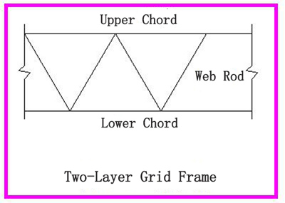
2.2 According to the number of chord layers,the grid frame can be divided into two-layer grid frame and three-layer grid frame.
2.2.1 The two-layer grid frame is a space structure composed of upper chord, lower chord, and web rod, which is a commonly used grid form.
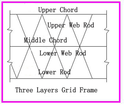
2.2.2 The three-layer grid frame is a space structure composed of upper chord, middle chord, lower chord, upper web rod and lower web rod.It is characterized by increasing the height of the grid frame, reducing the internal force of the chord, and reducing the mesh size and the length of the web rod. When the span of the grid frame is large, the amount of steel used for the three-layer grid frame is less than that of the two-layer grid frame. However, due to the increasing in the number of nodes and rod members, especially in the middle nodes, the number of links is large, which makes the structure complicated and the cost is improved.
2.3 Classification of grid frame
According to its shape, it can be divided into curved grid frame and flat grid frame.
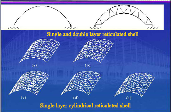
2.3.1 Curved grid frame(grid shell)
The curved grid frame is a curved steel structure composed of a rod according to a certain rule, which is divided into two types: single layer and double layer. The grid shell can be designed into a variety of curved surfaces to meet the structural and functional requirements of the building. The curved grid structure is mainly subjected to pressure, and the stability problem is more prominent. When the span is large, the strength of the material cannot be fully utilized. The initial deviations of rod members and joints, such as the geometrical deviation and the curved surface deviation, have a great influence on the internal force and overall stability of the curved grid frame. It uses a certain degree of arching to achieve the spatial transmission of external forces, while the extra upper convexity increases the building volume, but the huge thrust makes construction difficult and big material consumption.

National Grand Theatre (ribbed open double-layer grid shell)
2.3.2 Flat grid frame.(flat-panel grid frame)
The flat grid frame is a structure composed of rods according to a certain rule. The grid frame has multi-directional force transmission performance, large space rigidity, good integrity performance, and good seismic performance. It is suitable for both large-span buildings and small and medium-sized houses, covering various shapes of planes.
2.3.2.1 Planar truss grid frame
The upper and lower chords correspond exactly and are in the same vertical plane with the web rod. The vertical rod is pressed and the diagonal rod is pulled. The angle between the inclined web rod and the chord should be between 40° and 60°.
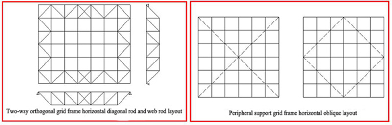
a. Two-way orthogonal spatial grid frame: vertical plane trusses in two directions intersect perpendicularly, parallel to the boundary direction. For the peripheral support grid frame, a horizontal diagonal strut should be set on the support plane (the plane formed by the chords connected to the support).
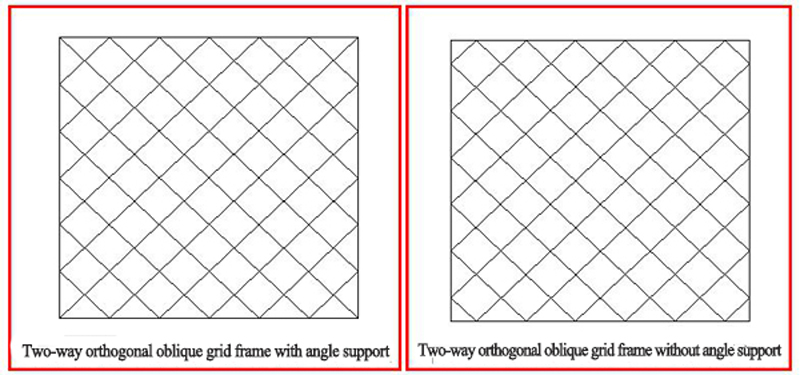
b. Two-way orthogonal oblique grid frame: The plane trusses in two directions intersect perpendicularly. When used in a rectangular building plane, the angle between the two-way truss and the boundary is 45°. In the two-way orthogonal oblique grid frame, the plane truss is obliquely intersected with the boundary,the lengths of the trusses are different, but the heights are basically the same. Therefore, the short trusses near the corners have relatively high rigidity,which take a certain support effect for the long trusses perpendicular thereto, thereby reducing the span cross-positive bending moment of long truss. Therefore, in the peripheral support, there is two layouts: long truss through the angular fulcrum (Fig. 5.1.5) and the avoidance angle fulcrum (Fig. 5.1.6). The former produces a large pulling force on the four-corner bearing, which the tensile force of the latter can be shared by two supports.
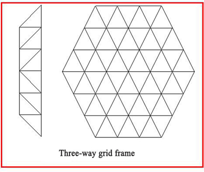
c. Three-way grid frame: The vertical plane trusses in three directions intersect each other at an angle of 60°. The grids in the upper and lower chord planes are all geometrically invariant triangles. Therefore, the grid is a geometrically invariant systems composed of a number of stable triangular prisms as the basic unit. The grid frame space has large rigidity, good force performance, and relative uniform internal force distribution, but the number of rod members that are connected to one node can’t be up to 13. The structure of the joint is more complicated, and it is preferable to use steel pipe rod members and welded hollow ball joints. The three-way grid frame is suitable for triangular, hexagonal, polygonal and circular building planes with large spans. When used in a circular plane, some irregular meshes will appear around the perimeter and need to be processed separately. The inter-section of the three-way grid frame is generally large, sometimes up to 6m.
2.3.2.2 Quadrangular cone system grid frame
This type of grid frame is composed of a number of inverted quadrangular pyramids (Fig. 5.1.8) based on a certain rule. The upper and lower chord planes of the grid frame are square grids, and the upper and lower chord grids are offset by half a grid. The lower chord nodes are all on the projection line of the upper chord grid centroid,which are connected with the four nodes of the upper chord grid by oblique web rods. Various forms of the quadrangular pyramid frame can be obtained by changing the position and direction of the upper and lower chords and appropriately extracting some chords and webs. The web rod of such grid frame generally do not have vertical bars, only diagonal bars. It is necessary to set the vertical web rod only when the upper and lower chord nodes are on the same vertical line.
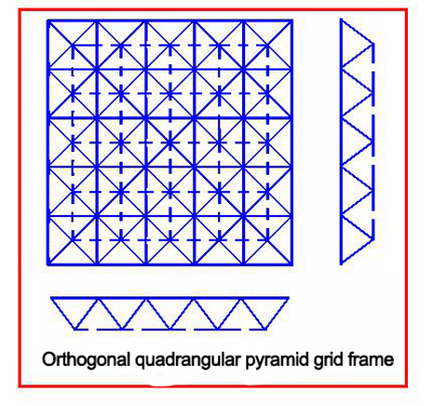
a.The orthogonal quadrangular pyramid grid frame: it is composed of the inverted quadrangular pyramid. The four sides of the cone bottom are the upper chord of the grid frame, and the cone rib is the web rod. When the building plane is rectangular, the upper and lower chords are parallel or perpendicular to the boundary. The upper and lower chord nodes are connected with 8 rods respectively, so the structure is relatively uniform. The stress of the square pyramid grid frame are relatively balance, and the plate has a single specification, which is convenient for arching. The roof drainage is relatively easy to handle, but the amount of steel used is relatively large due to the large number of rod members. It is suitable for medium and small span grids frame close to square,and perimeter support should be adopted.
b. Orthogonal evacuated quadrangular pyramid grid frame: On the basis of the orthogonal empty quadrangular pyramid grid frame, except for the surrounding mesh, properly remove some of the web and the lower chord rod. If removing the diagonal web and lower chord rod every other grid, the width of the lower chord grid is equal to twice the width of the upper chord grid, thereby reducing the number of rod members, the structure is simple, the economic effect is good, and the arching is convenient. A skylight or ventilation sunroof can be set in the evacuated area. Since the surrounding mesh is not suitable for removing the members, the number of grids in both directions should be odd.
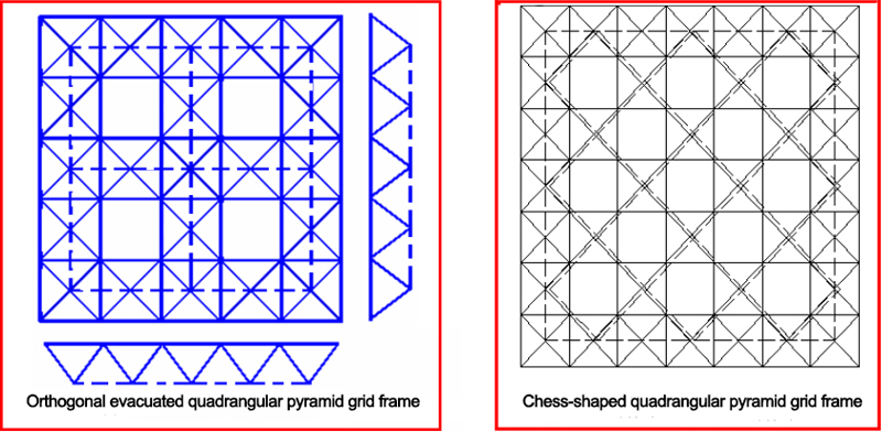
c. Chess-shaped quadrangular pyramid grid frame: On the basis of orthogonal empty quadrangular pyramid grid frame, the surrounding quadrangular pyramid is kept unchanged, and the middle quadrangular pyramid is evacuated at intervals. The upper chord rod is orthogonally placed, and the lower chord rod is at an angle of 45° to the boundary, which is obliquely placed orthogonally. As for this kind of grid frame, the upper chord short rod is pressed, and the lower chord long rod is pulled, and the rod crossed at the joint is less. This kind of grid also has the characteristics of short pressure rod and long puller rod. Since the surrounding is full of cones, its spatial effect is guaranteed. It is used for small span peripheral support situation.
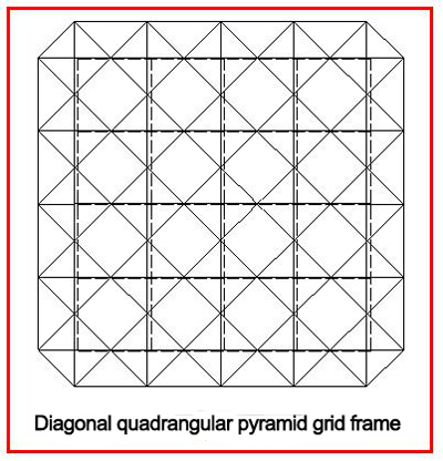
d. Diagonally quadrangular pyramid grid frame: The upper chord on the orthogonally quadrangular pyramid is rotated by 45° with respect to the boundary, and the diagonal quadrangular pyramid grid frame is obtained. The upper chord grid is orthogonally placed and the lower chord grid is orthogonally diagonally placed. The upper chord on the grid frame is short, the lower chord is long,so the force is reasonable. The lower chord node is connected to 8 rods, and the upper chord node is connected with only 6 rods. The number of rods at the joints is relatively less, so the amount of steel used is relatively low. However, when the reinforced concrete roof slab is selected, the orthogonal diagonally arrangement of the upper grid frame make the roof panel more specifications, thus causing the difficult in the roof drainage. If a metal plate such as a color profiled steel plate or a pressed aluminum alloy plate is used as the roof panel, this problem is easy to handle. When installing the diagonal pyramid grid frame, the whole lifting should be adopted. If you want to hoist the separate blocks, you need to add an auxiliary chain to prevent the block unit from being geometrically variable.
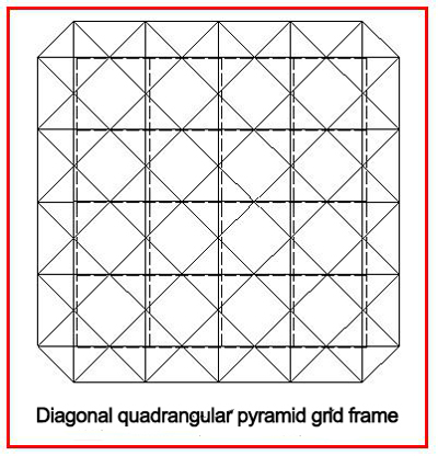
For a diagonal pyramid grid frame, when the aspect ratio is between 1 and 2.5, the internal force of the lower chord in the middle of long span is greater than the internal force in the middle of short span; when the aspect ratio is greater than 2.5, the opposite is true; When the ratio is between 1~1.5, the maximum internal force of the upper chord does not appear in the middle of the span, but in the middle of the 1/4 plane of the grid frame. As for the surrounding supported quadrangular pyramid grid frame, when the support is tangentially unconstrained along the circumference, the periphery can rotate the Z-axis to make the geometry of the grid variable . Therefore, a steel rigid side beam must be arranged around the grid frame. As for the point-supported diagonal quadrangular pyramid grid frame, a closed side truss at the periphery should be set to keep the geometry of the grid frame unchanged.
The oblique quadrangular pyramid grid frame is generally suitable for a medium-small-span peripheral support, or a rectangular plane which combines a peripheral support and a point support.
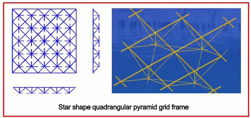
e. Star shape quadrangular pyramid grid frame: Replace the four rods (upper chord) on the bottom of the quadrangular pyramid with a cross bar on the diagonal line, and add a vertical rod at the center to form a star shape quadrangular pyramid. The cross bar (upper chord) is at an angle of 45° to the boundary, forming a grid frame upper chord, which is placed orthogonal diagonally. The lower chord is placed orthogonally. The web rod is in the same vertical plane as the upper chord. As for the star shape grid frame, the upper chord is shorter than the lower chord, so the force is reasonable. The upper chord is generally stressed, but it may be pulled at the corners. The force situation is close to the cross beam system, but the stiffness is slightly worse than the orthogonal quadrilateral pyramid grid frame. When the height of the grid frame is equal to the length of the upper chord, the upper chord is equal to the length of the vertical rod, and the oblique rib is the same length as the lower chord. The star shape grid frame is generally used for medium-small-span peripheral support.
2.3.2.3 Triangular cone system grid frame
The basic unit of the triangular cone system grid frame is an inverted triangular cone with an equilateral triangle at the bottom (Fig. 5.1.14a).
The three sides of the cone bottom are the upper chords of the grid frame, and the edges are the web rod of the grid frame. With the different arrangement of the triangular cone units, the upper and lower chord grid frame can be equilateral triangles or hexagons, thus forming different triangular cones grid frame. There are three main types of frames: a triangular cone grid frame, an evacuated triangular cone grid frame, and a honeycomb triangular cone grid frame.
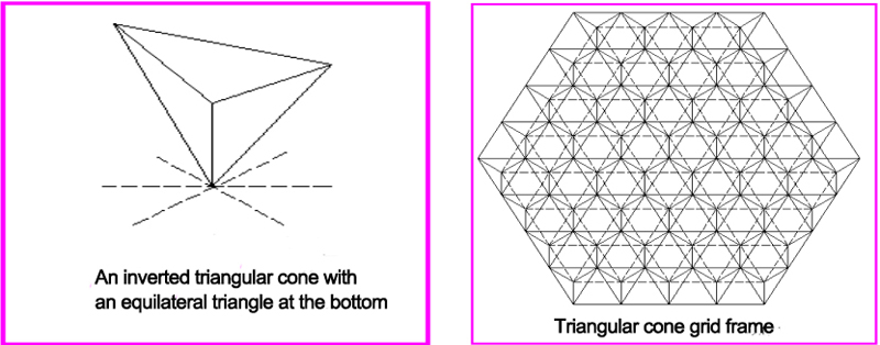
a. Triangular cone grid frame
The upper and lower chord planes of the triangular cone grid frame are all equilateral triangle grid frame, and the upper and lower chord nodes are connected with 9 bars, and the node structure is more complicated. When the height of the grid frame is / 2/3 times the grid size, the upper and lower chords are equal in length to the web rod. The triangular cone grid frame has uniform force, good integrity and torsional rigidity, and is suitable for large and medium-span buildings with polygonal planes.
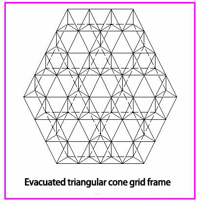
b. Evacuated triangular cone grid frame
Keep the upper chord grid of the triangular cone grid frame unchanged, and extract some of the web and lower chords according to a certain rule to obtain the evacuated triangular cone grid frame.
For example, the rod extracted method shown in Figure 5.1.15 is that the grid around the grid frame is not extracted and the inner part is removed part of the rod every grid from the second circle along the three directions. Then the lower chord grid frame will become the combination of polygons. After the rod is extracted, the space rigidity of the grid frame is weakened. The number of lower chords is reduced and the internal force is large. The upper chord grid is denser, which is convenient for laying the roof panel. The lower chord grid is sparse, so as to save the steel and form the evacuated triangular cone grid frame.It is suitable for medium and small span buildings with polygonal planes.
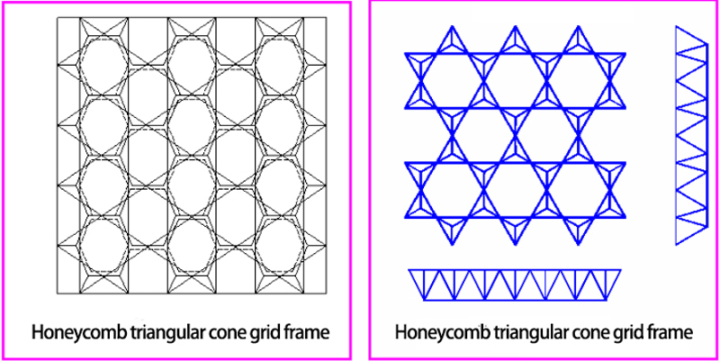
c. Honeycomb triangular cone grid frame
The upper chord is a triangle and a hexagon, and the lower chord is a hexagon. The web rod and the lower chord are in the same vertical plane. The number of nodes and rods is less, suitable for peripheral support, and medium and small span roof. The honeycomb triangular pyramid grid frame itself is geometrically variable, and it has to be kept unchanged by means of the horizontal constraint of the support.
3. Selection of grid frame steel structure
When choosing the form of the grid frame steel structure, the following factors should be considered: the plane shape and size of the building, the support way of the grid frame, the load size, the roof structure, the building structure and requirements, the production and installation methods, and the material supply situation. According to the "Technical Regulations for Space Grid Frame Structure" (JGJ 7-2010): the long span is more than 60m; the mid-span is 30~60m; the small span is less than 30m.
As for the peripheral support grid frame with a rectangular shape plane, when the side length ratio (long side/short side) is less than or equal to 1.5, it is preferable to use a orthogonal or a diagonal pyramid grid frame, a checkerboard quadrangular pyramid grid frame, and a orthogonal evacuated quadrangular pyramid grid frame, two-way orthogonal oblique or orthogonal grid frame. For medium and small spans, a star-shaped quadrangular pyramid grid frame and a honeycomb triangular pyramid grid frame can also be used.
As for the peripheral support grid frame with a rectangular shape plane, when the side length ratio is greater than 1.5, the two-way orthogonal grid frame should be selected, and the orthogonal quadrangular pyramid grid frame or the orthogonal evacuated quadrangular pyramid grid frame. When the side length ratio is not more than 2, the orthogonal quadrangular pyramid grid frame can also be used.
As for the grid frame with rectangular shape and multi-point support plane, a orthogonal quadrangular pyramid grid frame, four-cornered cone grid,the orthogonal evacuated quadrangular pyramid grid frame, and two-way orthogonal grid frame should be adopted. The multi-span grid frame combined with the multi-point support and the peripheral support may also be a two-way orthogonal oblique grid frame or a diagonal quadrangular pyramid grid frame.
As for the periphery support grid frame with circular shape, a regular hexagon and a nearly hexagonal shape, a three-way grid frame , a triangular pyramid grid frame or an evacuated triangular frame grid can be selected. Honeycomb triangular pyramid grid frame are also available for medium and small spans.
3.1 Support of grid frame steel structure
The support way of the grid frame includes peripheral support, point support, combination of peripheral support and point support, two-sided and three-sided support.
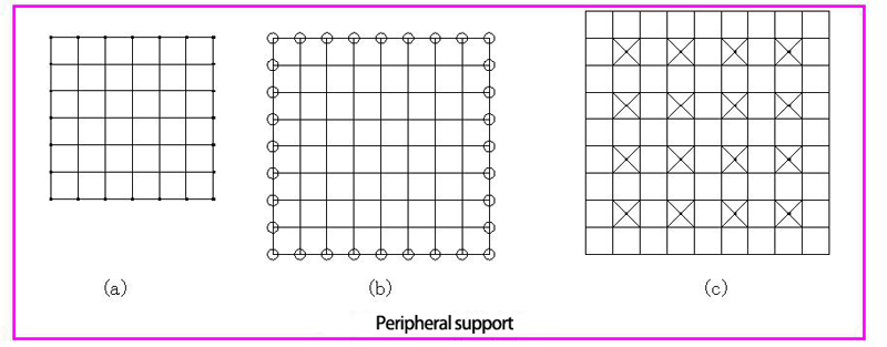
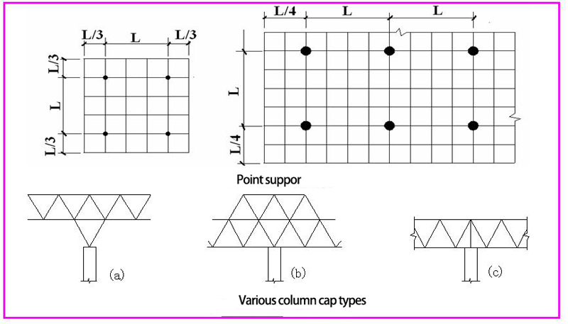
3.1.1 Peripheral support: Supports are provided at all or part of the boundary nodes around the grid frame (Fig. 5.1.17a, Fig. 5.1.17b). The support can be supported on the top of the column or on the ring beam. The grid frame force is similar to the four-sided support plate, which is a commonly used support method. In order to reduce the bending distance, the peripheral support can also be slightly retracted, as shown in Figure 5.1.17c, this kind of arrangement is very close to the point support.
3.1.2 Point support grid frame: can be placed on four or more supports, the former is called four-point support grid frame, the latter is called multi-point support grid frame. The force of point support grid frame is similar to the reinforced concrete beamless floor cover. To reduce the bending distance and deflection of mid-span, the cantilever length of the multi-point support grid frame can take 1/4~1/3 of the span (Fig. 5.1.18). . The point support grid frame should be connected to the column, and a column cap should be provided to reduce the punching and shearing action.
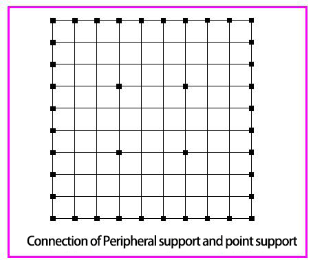
3.1.3 Peripheral support and point support mixed grid frame: It means that in the point support grid frame, when there is no maintenance structure and wind-resistant column surrounding, the mixed form of peripheral support and point support can be adopted. This type of support is suitable for public buildings such as steel structure workshop and exhibition halls. (Figure 5-20)
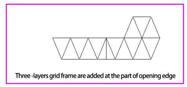
3.1.4 Three-sided support or two-sided support grid frame(Fig. 5.1.21)
In a rectangular plane building, due to the possibility of expansion or the requirements of the building function, it is necessary to open on one side or two pairs of sides, so that the grid frame is supported on only three or two pairs of sides, the other side or two pairs of sides will be act as a free edge. Increasing the number of layers of the grid frame near the free edge, or add joists and brackets on the free side. For medium and small grid frame, it can also be improved and strengthened by the method of increasing the height of the grid frame or partially increasing the cross section of the rods.
4. Height of grid frame and size of grid
The height of the grid frame is related to factors such as roof load, span, plane shape, support conditions and equipment piping.
When the roof load is large and the span is large, the height of the grid should be larger. When the plane shape is circular, square or close to a square, the height of the grid frame can be made smaller. When the plane is narrow and long, the one-way transmission force is obvious, so the height of the grid frame should be larger.
The height of point support grid frame is larger than the peripheral support grid frame. When there is a running pipe in the grid frame, the height of the grid frame should meet the requirements. The grid size of the grid frame is closely related to the height and directly affects the economics of the grid frame. The angle between the inclined web rod and the chord should be controlled between 40° and 55°. If the angle is too small, the node construction will be difficult.
The grid size should be compatible with the roof material. When the reinforced concrete slab is directly laid on the grid frame, the grid size should not be too large, generally not more than 3m, otherwise the installation is difficult. When the roof is made of a purlin system, the length of the purlin is generally not more than 6m.
The height of the various peripheral support grid frame and the grid size can be selected according to table.
| Number of chord grids and span ratios of the grid frame | ||||
|---|---|---|---|---|
| Type Of grid frame | Steel reinforced concrete roof system | Steel purlin roof system | ||
| Number of grids | Span ratio | Number of grids | Span ratio | |
two-way orthogonal grid frame orthogonal quadrangular pyramid grid frame orthogonal evacuated quadrangular grid frame |
(2~4)+0.2L2 | 10~14 | (6~8)+0.07L2 | (13-17)-0.03L2 |
two-way orthogonal oblique grid frame Chess-shaped quadrangular pyramid grid frame oblique quadrangular pyramid grid frame star-shaped quadrangular pyramid grid frame |
(6~8)+0.08L2 | |||
Notes:
1. L2 is the short side span of grid frame, the unit is m.
2. When the span is below 18m, the number of grids can be reduced appropriately.
5. Grid frame deflection requirements and roof drainage slope
5.1 The allowable deflection of the grid frame steel structure shall not exceed the following values: for the roof - L2 / 250; for the floor - L2 / 300. L2 is the short span of the grid frame.
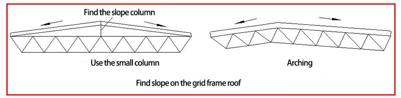
5.2 The drainage slope of the grid frame roof is generally 3%~5%. The following methods can be used to find the slope:
Adding small columns of different heights on the upper chord (Fig. 5.1.22a). When the small column is high, the stability of the small column itself should be noted; arching the entire grid frame (Fig. 5.1.22b); using variable height grid frame, increasing the mid-span height of the grid frame, so that the upper chord forms a slope, and the lower chord is still parallel to the ground, similar to a trapezoidal truss. A grid frame with arching requirements may have a arching degree of no more than 1/300 of the short span.
6. Load and Function of grid frame steel structure
6.1 Function and Type of load
The loads and functions of the grid frame structure mainly include permanent loads, variable loads, temperature and earthquakes functions. Calculate the internal forces and displacements under the load during the use phase, and calculate the internal forces and displacements caused by seismic action, temperature change, bearing settlement and other indirect effects as well as construction and installation loads according to the specific conditions.
The standard value of the grid frame self-heavy load (kN/m2) can be estimated as follows:
Gok=√qw· L2/150
Qw: standard value (kN/m2) of roof load (or floor load) except the weight of the grid frame itself
L2: short span of the grid frame(m);
Gok: standard value of the self-heavy load of the grid frame(kN/m2)
6.1. 1 Permanent load: including the weight of the grid frame itself, the material gravity of the roof (or floor) , the gravity of the ceiling material, and the gravity of the equipment pipe.
6.1.2 Variable load: including roof (or floor) live load, snow load (snow load should not be combined with roof live load), wind load. due to the large rigidity of the grid frame, the natural vibration period is small, the influence of the wind vibration coefficient, the ash load and the crane load (considered when the industrial building has a crane) can be ignored when calculating the wind load.
6.1.3 In the area where the seismic fortification intensity is 6 degrees or 7 degrees, the grid frame roof structure may not be subjected to vertical anti-seismic check; in areas where the seismic fortification intensity is 8 degrees or 9 degrees, the grid frame roof structure shall be subjected to vertical anti-seismic check.
6.1.4 For the peripheral support grid frame roof panel and combination of the multi-point support and peripheral support grid frame roof panel, the standard value of vertical seismic action can be determined as follows:
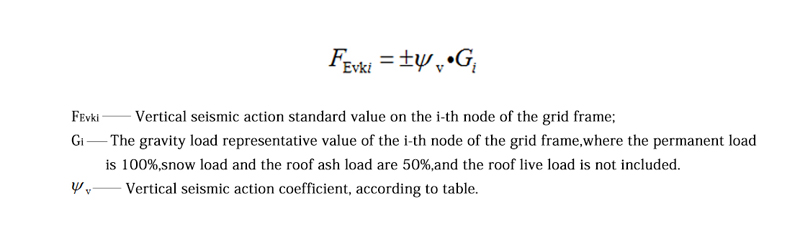
| Vertical seismic action coefficient | |||
|---|---|---|---|
| Fortification intensity | Site type | ||
| 1 | 2 | 3,4 | |
| 8 | can’t be calculated(0.10) | 0.08(0.12) | 0.10(0.15) |
| 9 | 0.15 | 0.15 | 0.20 |
Notes: The values in parentheses are used in the district with a design of 0.3g basic seismic acceleration.
6.1.5 For the grid frame roof structure with large cantilever length and the grid frame structure for the floor, when the fortification intensity is 8 degrees or 9 degrees, the vertical seismic action standard value can take the 10% or 20% of the representative gravity load of the structure. When the design basic seismic acceleration is 0.3g, 15% of the representative value of the gravity load of the structure can be taken.
For the large-span grid frame structure with complex or important planes, the vibration-decomposition reaction spectrum method or time-course analysis method can be used for special vertical seismic analysis and check calculation.
6.1.6 In the area where the seismic fortification intensity is 7 degrees, the horizontal seismic comprehension of the grid frame structure may not be carried out; in the area where the seismic fortification intensity is 8 degrees, the horizontal seismic comprehension may be not performed for the medium and small span grids frame supported by the surrounding; For areas with a seismic fortification intensity of 9 degrees, horizontal seismic comprehension should be performed for various grid frame structures. The internal force and displacement of the grid frame under horizontal earthquakes can be calculated by the space truss displacement method. The support structure of the grid frame shall be subjected to seismic verification in accordance with the relevant regulations.
6.2 The following conditions of the grid frame structure unconstrained or not constrained by deformation may not consider the internal force caused by temperature changes:
6.2.1 The construction of the support node allows the grid frame to move sideways;
6.2.2 The peripheral grid frame, when the grid frame inspection direction span is less than 40m, and the support structure is independent column or brick wall column (these columns have certain flexibility);
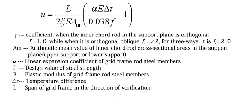
6.2.3The top column under the action of unit force, the displacement is greater than or equal to the calculated value of the following formula (the temperature stress caused by the constraint of the column is not large);
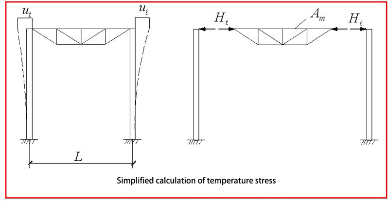
6.3 If it is necessary to consider the internal force of the grid frame caused by temperature changes, the space truss displacement method, or approximate calculation method may be used. For the peripherally hinged grid frame, the space grid frame and support structure can be simplified to the plane frame shown in Figure for analysis. The temperature stress of the grid frame is caused because the support structure hinder the temperature expansion and contraction of the inner chord in the grid support surface.
If the temperature expansion and contraction of the inner chord in the grid frame support plane is unimpeded, the top of the column moves outward when the temperature rises at △tC:
In the u0t = a△tL/2, a is the coefficient of linear expansion of the steel, L is the span of the grid frame.
The constraining action of the column makes this displacement not fully develop and generates a stress σ in the chord of the bearing surface, resulting in an actual displacement of ut=(a△t-σt /E)L/2
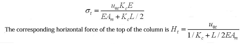
If the lateral stiffness of the column (the horizontal force that causes the unit displacement of the column top) to be Kc, then the equilibrium condition of the horizontal force of the column top is σ_Am=KcUt
In the formula, Am is the cross-sectional area of the chord rod, and σt is the chord temperature stress, then which can obtained by the above two formulas
6.4 For grids frame with non-seismic design, the combination of load and load effect shall be calculated in accordance with the provisions of the National Standard “Building Structure Load Code” (GB50009-2012).
6.5 For the grid frame with the seismic design, the combination of load and load effect should also meet the requirements of the national standard “Code for Seismic Design of Buildings” (GB50011—2010).
The standard value of the grid frame self-heavy load (kN/m2) can be estimated as follows:
Gok=√qw· L2/150
qw: standard value (kN/m2) of roof load (or floor load) except the weight of the grid frame itself
L2: short span of the grid frame(m);
Gok: standard value of the self-heavy load of the grid frame(kN/m2)
7. Grid frame internal force analysis method:
7.1 As for space grid frame structure, the joints can be assumed as hinged, ie ignoring the effects of node stiffness. All the rods are elastic, ie the nonlinear nature of the material is not taken into account. Since the deflection of the grid frame under load is much smaller than the thickness of the grid frame, it can be considered to meet the small deflection range. Therefore, assuming that the joint is hinged, the rod only bears the axial force. When the inter-section load acts on the rod, the influence of the bending distance should be considered at the same time.
7.2 The internal forces and displacements of the grid frame can be calculated according to the elastic phase. According to the grid frame type and span size, different calculation methods are selected according to the following regulations.
7.2.1 Space truss displacement method (space rod finite element method) is the most accurate method for calculating the grid frame structure. It is suitable for grid frame computing of various types and various supporting conditions.
7.2.2 Cross beam system difference method is a simplified calculation method, which can be used for the calculation of a grid frame consisting of a plane truss system whose span is less than 40m or a quadrangular pyramid grid frame.
7.2.3 The proposed sandwich panel method is another simplified calculation method, which can be used for the calculation of grids frame composed of plane trusses whose span is less than 40m or pyramids grid frame.
7.2.4 The imaginary bending distance method is also a simplified calculation method, which can be used for the estimation of the diagonal pyramid grid frame and the checkerboard quadrangular cone grid frame.