Design of steel structure column and support
- 05 Sep 2020
- steel structure
1. Outline of frame column design
★ Column section form: box, welded I-section, H-beam, round pipe, etc
★ Estimation of section: according to 1.2N axial compression member, the section of 3 ~ 4 layers should be changed once, and the thickness should not exceed 100 mm
★ The width thickness ratio of plate is shown in the table below
★ The slenderness ratio: the frame column of multi-storey (﹥ 12 storey) should not be greater than 120 when it is 6-8 degrees of fortification, and should not be greater than 100 degrees of fortification at 9 degrees. When the fortification intensity is 6, 7, 8 and 9, the frame columns of high-rise buildings (> 12 stories) are 120, 80 and 60.
★ Technical specification for steel structure of high-rise civil buildings(JGJ99-98) stipulates: when calculating the stability under the combination of gravity, wind or frequent earthquake load, if the standard value of story displacement does not exceed 1 / 250 of storey height, the effective length coefficient of frame column with brace (or shear wall) can be taken as M = 1.0; when the standard value of story displacement does not exceed 1 / 1000 of storey height, the effective length system of pure frame column is adopted The number can also be determined by Wu's formula.
★ The braced frames in GB 50017 are divided into strong braced frames and weakly braced frames.
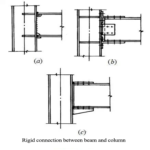
2. Connection between column and beam
★ Common form: rigid connection
★ Practice:
★ Full welding
★ Fully bolted
★ Mixing of bolt and welding
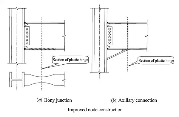
★ Improved form full welding
Dog bone
Haunching of beam end
Cantilever beam section
★ Flexible connection form:
Connecting angle steel
End plate
Buttress
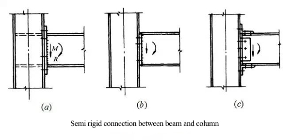
★ Semi rigid connection:
End plate high strength bolt connection mode
Upper and lower angle steel and high strength bolt
3. Upper and lower angle steel and high strength bolt
★ Type: transverse horizontal support, longitudinal horizontal support
★ Function:
★ Temporary horizontal support: it is set for the safety of construction and installation and removed after construction;
★ Permanent horizontal support: it is set when horizontal members (such as floor or roof components) cannot form diaphragms with high horizontal stiffness
Form: plane truss
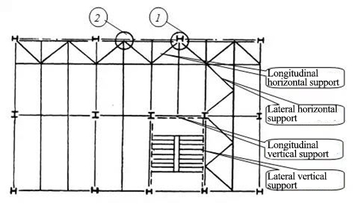
4. Vertical support design
★ Composition:
It is usually a plane truss that runs through the whole height of the building. It is composed of a series of diagonal web members between two column members
★ Classification:
Vertical center support and vertical eccentric support
★ Layout:
It can be arranged between columns in the longitudinal part of the building, or in the horizontal or vertical and horizontal directions; its position on the plane can be arranged along the outer wall or along the inner wall
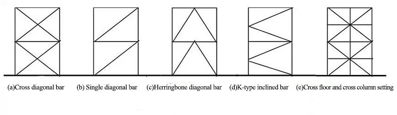
5. Central support
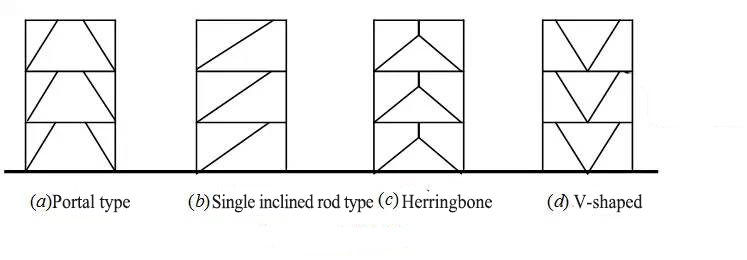
★ Form:
The system of cross diagonal bar (figure a), single diagonal bar (Figure b), herringbone diagonal bar (or V-shaped inclined bar, figure C) or K-shaped inclined bar (Figure d) system
★ The K-shaped inclined bar system shall not be used in the seismic fortification structure
★ The supporting system can be set across floors and columns
★ Slenderness ratio:
Non seismic fortification structure: the slenderness ratio of tension member shall not be greater than 300, and the slenderness ratio of tension and compression member shall not be greater than 150
Seismic fortification structure:
| Limit of slenderness ratio of central support member | ||||
|---|---|---|---|---|
| type | 6,7 degrees | 8 degrees | 9 degrees | |
| Multi-storey(≤12 layers) | Press bar design | 150 | 120 | 120 |
| pull rod design | 200 | 150 | 150 | |
| high-level(≥12layers) | 120 | 90 | 60 | |
★ Width thickness ratio of plate:
6 degree seismic fortification and non seismic fortification: according to code for design of steel structures (GB 50017)
Seismic fortification structure
| Width thickness ratio limit of central support plate | |||||||
|---|---|---|---|---|---|---|---|
| Plate name | multi-storey(≤12 layers) | high-level(≥12layers) | |||||
| 7 degrees | 8 degrees | 9 degrees | 6 degrees | 7 degrees | 8 degrees | 9 degrees | |
| Flange overhang | 13 | 11 | 9 | 9 | 8 | 8 | 7 |
| I-section Web | 33 | 30 | 27 | 25 | 23 | 23 | 21 |
| Box section Web | 31 | 28 | 25 | 23 | 21 | 21 | 19 |
| Ratio of outer diameter to wall thickness of round pipe | 42 | 40 | 40 | 38 | |||
Form of section:
Biaxial symmetric section
The single axis symmetrical section is adopted to prevent buckling around the symmetric axis
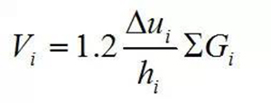
★ Additional effects caused by P - △ effect:
Under gravity and horizontal force, the additional bending effect caused by horizontal displacement and gravity load is not only subjected to shear force caused by horizontal load, but also subjected to additional bending effect caused by horizontal displacement and gravity load
The vertical load of the floor from the support span beam should also be considered for the herringbone and V-shaped support.
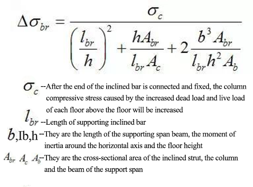
The additional compressive stress caused by the elastic compression deformation of the column under gravity should be included in the inclined bar of cross bracing, herringbone support and V-shaped support
Diagonal bar for cross bracing
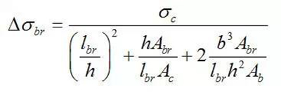
For diagonal members of herringbone and v-brace
Under the combined action of frequent earthquake effects, the internal forces of diagonal members of herringbone brace and V-shaped brace should be multiplied by 1.5
★ The supporting inclined rod is checked according to the compression bar

For the central support system with energy dissipation device, the bearing capacity of the diagonal bar should be 1.5 times of the bearing capacity of the energy dissipation device when sliding or yielding.
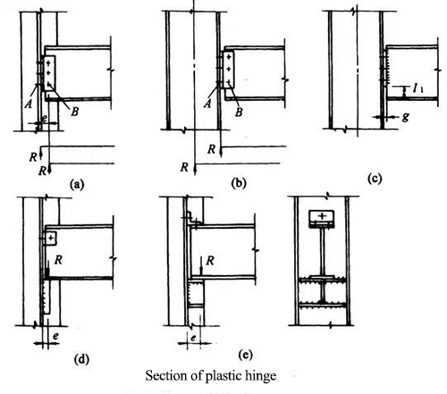
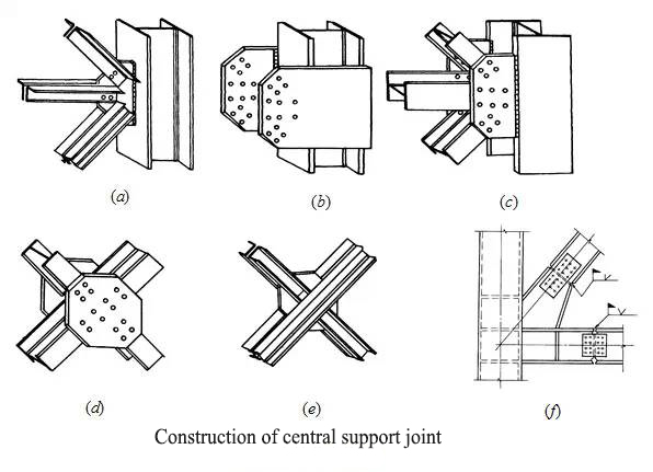
★ Construction of central support joint
6. Eccentric support
★ Form:
Portal frame (Fig. a), single inclined pole (Fig. b), herringbone (Fig. C) or V-shaped (Fig. d)
★Features:
★ The inclined strut is not intersected with the beam column join
★ The energy dissipation beam section: under normal load state, the eccentrically braced frame has enough horizontal stiffness; when encountering strong earthquake action, the energy dissipation beam segment first yields to absorb energy
★ Slenderness ratio: no more than 120
★ The width thickness ratio of plate: it shall not exceed the width thickness ratio limit of axial compression member in elastic design specified in GB 50017
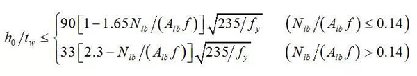
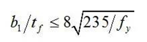
★ Local stability of energy dissipation beam section
The ratio of free overhanging width B1 to thickness TF of flange plate:
The ratio between the calculated height of web plate H0 and its thickness TW: