Design and calculation of space truss steel structure
- 17 Sep 2019
- steel structure
1. Computational model and analysis method of space truss
1.1 Computational model of space truss
1.1.1 The calculating model of articulated pole system: The lattice steel structure is regarded as a set of articulated poles. According to the working state of each pole, the working state of the whole lattice structure can be obtained. By using each pole as a basic element of the calculation of the lattice structure. This calculation model is used for the members in the displacement method of space truss.
1.1.2 Truss calculation model: According to the law of the composition of the truss, the truss is regarded as a set of truss systems, and a section of truss is considered as a basic unit in the analysis. For example, the orthogonal space truss can adopt this model, which is more convenient in simplifying calculation.
1.1.3 Beam system calculation model: The grid structure is replaced by beam system by conversion method, and then the beam section is taken as the basic element of calculation and analysis. This computational model has been applied to some differential classification methods, such as the cross-system difference method.
1.1.4 Plate calculation model: Similar to beam system calculation model, there is a process of converting space truss into plate. This model has been applied in early theoretical analysis of space truss, such as sandwich plate method and quasi-laminated plate method.
1.2 Analytical method of space truss structure
1.2.1 Finite Element Method: According to the different elements used in the bar, it can be further divided into the bar finite element method and the beam finite element method.
1.2.2 Force Method: The force method in classical structural mechanics is used to solve the problem.
1.2.3 Differential method: Differential equation is solved by difference method.
1.2.4 Analytical method of differential equation: approximate solution of differential equation, such as variational method, weighted parameter method, etc.
1.3 Displacement Method of Space Truss
Method Introduction: The basic element is the member of the space truss, and the displacement of the node is the basic unknown quantity. Firstly, the element stiffness matrix is established based on the relationship between the internal force of the member and the displacement of the node. Then, the relationship between the node load and the node displacement is established according to the equilibrium and deformation compatibility conditions of the nodes, and the total stiffness matrix and the total stiffness equation of the structure are formed. The total stiffness equation is a set of linear equations with node displacement as an unknown variable. After introducing boundary conditions, the displacement values of each node are solved. Finally, the internal force of the member is obtained from the relationship between the internal force of the member element and the displacement of the node.
The finite element method of space bar system is applicable to all kinds of space trusses with different plane shapes and boundary conditions. Static load, earthquake action, temperature stress and other conditions can be calculated, and the joint work of space truss and lower supporting structure can also be considered.
1.3.1 Basic assumptions
The joints of space truss are articulated, and each node has three degrees of freedom, ignoring the influence of joint stiffness; the load acts on the nodes of space truss, and the members only bear the axial force; the material works in the elastic stage, which conforms to Hooke's law; the deformation of space truss is very small, and the influence caused by it is neglected, regardless of its geometric nonlinearity.
1.3.2 Element stiffness matrix
Single Rigid Matrix in Local Coordinate System of Bars: Finite Element of Space Bar System, 6 Degrees of Freedom of each Bar corresponds to 6 End Forces and 6 End Displacement
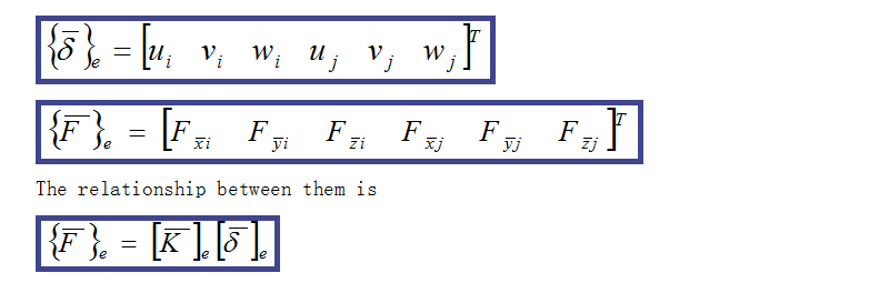
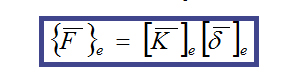
Let F, δ and K represent the nodal forces, nodal displacements and element stiffness matrices of member ij in the global coordinate system, respectively. In the global coordinate system, the relationship force between the joint force and the joint displacement of ij bar is as follows:
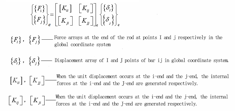
1.3.3 Total Stiffness Matrix and Equation of Structural Stiffness
In the global coordinate system, the relationship force between the joint force and the joint displacement of ij bar is as follows
1.3.4 The total rigid matrix has the following characteristics:
Matrix is symmetrical, so it is not necessary to list all elements in calculation, but only the upper triangle or the lower triangle. Matrix is sparse. Due to the limited number of connecting rods at each node of space truss structure, all elements in the total rigid matrix are zero except the principal diagonal and its adjacent elements. The non-zero elements are concentrated in the zonal area on both sides of the main diagonal line. When computer is stored in one-dimensional variable bandwidth, the computer capacity can be effectively saved. The bandwidth size is related to the node number of the grid. When the node number of the grid is numbered, the difference between the relevant node numbers should be reduced as far as possible.
1.3.5 A Method of Processing Boundary Conditions in Structural Total Rigid Matrix
Displacement is zero: row and column method and multiplier method.
Elastic constraints: Spring stiffness K0 is superimposed on the corresponding principal diagonal elements in the total rigid matrix.
Designated Displacement: Principal Diagonal Element and Right Term Multiplied by Large Number R
2. Boundary Conditions and Symmetry Utilization of Space Truss
2.1 Symmetry Utilization: When the space truss structure (including the support) and the external load have a symmetrical surface, only 1/2n of the space truss can be analyzed by symmetrical condition.
When calculating, the cross-sectional area of each member in the symmetrical plane should be half of the original cross-sectional area, and that of the central vertical bar on the intersection line of N symmetrical planes should be 1/2n of the original cross-sectional area. The load of symmetrical in-plane joints should also be calculated according to the same principle. Under symmetrical load, the anti-symmetrical displacement of symmetrical in-plane space truss joints is zero, which should be constrained in the corresponding direction. When a bar intersects a symmetrical plane, the intersection point can be regarded as a node and constrained in three directions. When the intersection point of the cross web or herringbone web is located on the symmetrical plane, it also acts as a node and is constrained in two horizontal directions. Under the action of anti-symmetrical load, the symmetrical displacement of the node of the symmetrical in-plane space truss should be zero.
2.2 boundary condition
The boundary conditions at the support of space truss are related not only to the structure of support nodes, but also to the stiffness of support structure. The support can be articulated support without lateral displacement, one-way lateral displacement and two-way lateral displacement, and the support structure (columns, beams, etc.) can be rigid or elastic.
When the stiffness of the supporting structure is large enough to neglect its deformation, the boundary conditions depend entirely on the support structure:
2.2.1 When the non-lateral hinged bearing is used, the supporting nodes are vertical, and the tangent and normal of the boundary line are not displaced.
2.2.2 When the one-way lateral movable support is used, the vertical and tangential displacement of the boundary is zero, while the normal direction of the boundary is free.
2.2.3 When the two-way lateral displacement articulated support is adopted, only the vertical displacement is zero and both horizontal directions are free.
2.2.4 At the four corners of the grid, the bearings at at least one corner must be non-lateral, which not only prevents the rigid body of the grid from moving, but also provides not less than six restraint chains. In engineering practice, if the temperature stress condition does not need to be calculated, it can also be considered that all corners are supported with no lateral hinges.
2.2.5 When the latter is supported on an independent column, the flexural stiffness of the latter is not very large. When the latter is adopted, except that the vertical direction is still considered as no displacement, the two horizontal directions should be considered as elastic support. The spring stiffness of the support is derived from the deflection formula of the cantilever column.
2.3 Oblique boundary treatment:Oblique boundary refers to the boundaries that are constrained in the direction of oblique intersection with the global coordinates. There are two methods to deal with oblique boundary:
2.3.1 An additional bar with a certain section area is set according to the displacement constraint of the boundary point. If the displacement of the node is zero along the normal direction of the boundary, an additional bar with a large stiffness is set in the direction. If the node is elastically constrained along the normal direction of the boundary, the section area of the additional bar is adjusted to satisfy the elastic constraint condition. The stiffness matrix is sometimes ill-conditioned by this method.
2.3.2 Another method is to do coordinate transformation of node displacement on oblique boundary, which transforms node displacement vector in global coordinates into any oblique direction, and then treats it according to general boundary conditions.
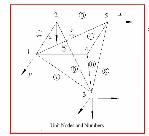
3. Calculation steps of finite element method of space truss system (displacement method of space truss)
Computing sketch, numbering nodes and members;
Calculate the length of member element and the angle cosine between member and integral coordinate axis.
The cross-sectional area of each rod is selected.
The element stiffness matrices in local and global coordinates are established.
The aggregate total rigid matrix is stored in one-dimensional storage mode with variable bandwidth.
Establishment of load array;
The boundary condition is introduced to deal with the total stiffness equation.
The total stiffness equation is solved and the displacement values of each node are obtained.
The internal force of the member is calculated according to the displacement of the node.
The internal force of the member adjusts the section of the member and recalculates it. The number of iterations should not exceed 4-5 times.
4. Members Design and Joint Construction of Space Truss Structures
4.1 Bar design of space truss structure
The main materials of space truss members are Q235 steel and Q345 steel.
The cross-section of space truss members is round, T-shaped by two equal-limb angle steels, T-shaped by two unequal-limb angle steels, single-angle steels, section steels and square pipes.
The circular tube section has the characteristics of large turning radius and non-directional cross-section characteristics. It is the most commonly used cross-section at present. Under the condition of equal cross-section area, the bearing capacity of circular pipe under axial compression is 1.2-2.75 times that of T-section composed of two equal-limb angle steels.
Thin-walled square tube section has the characteristics of large turning radius and equal turning radius in both directions. It is a more economical section. At present, there is little research on the nodal form of this section in China and its application is not extensive.
T-section made of angle steel is suitable for plate joint connection. Because of the large workload of welding on site, the fabrication of angle steel is complex and less used. Single angle steel is suitable for web members with less stress. H-section steel is suitable for chord with larger force.
4.2 The slenderness ratio of space truss members should not exceed the following values
Compressed member:180
Tension member:General member 300; member 250 near support; member 250 directly bearing dynamic load
The members of space truss are mainly subjected to axial force. The calculation of section strength and stability should meet the requirements of the Code for Design of Steel Structures (GB50017-201X). The minimum cross-section size of ordinary angle steel bars should not be less than 50 mm x 3 mm, and the steel tube should not be less than 48 mm x 3 mm. For large and medium span space grid structures, the steel tube should not be less than 60 x 3.5mm.
4.3 Node design of space truss
The joint acts as a connecting link between intersecting poles and transfers roof load and crane load. There are 6 to 13 members joined at one node, which makes joint design more difficult. The number of grid joints is large, and the amount of steel used for joints accounts for about 20%~25% of the total amount of steel used for grid structures. Reasonable design of joints has a direct bearing on the safety, fabrication and installation of the grid, the progress of the project, the steel consumption index and the cost of the project.
4.3.1 Node form of space truss:
JGJ7-2010 Code adds cast steel joints, pin-type joints and prestressing cable joints.
4.3.2 Node forms commonly used in China at present:
Welded hollow spherical joints; Bolted spherical joints; Welded steel plate joints; Welded steel pipe joints; Bar directly joints.
4.4 Node construction of space truss shall meet the following requirements:
Reasonable force and clear force transmission; ensure that the poles meet at one point without additional bending moment; simple structure, easy fabrication and installation, low steel consumption; avoid dead angles or grooves that are difficult to inspect, clean, paint and easy to accumulate moisture or dust, and the tubular section should be closed at both ends.
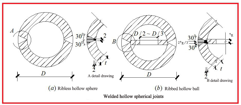
4.4.1 Welded hollow spherical joints
Welded hollow spherical joints are directly welded to hollow spherical joints by the steel pipe bars which intersect at the joints. The structure of the joints is simple. It has clear force transmission, simple structure, convenient connection and strong adaptability. As long as the cutting surface of the steel tube is perpendicular to the axis of the rod, the rod can be naturally centered on the hollow sphere without eccentricity, and can be connected with the rod in any direction.
However, due to the large amount of steel used in joints, upside-down welding and vertical welding account for a large proportion; the length of rod blanking is required to be accurate; the dimension deviation will occur due to welding deformation, and the welding deformation allowance should be reserved.
Welded hollow spheres are formed by hot pressing two steel plates into two hemispheres and then welding each other. It can be divided into two kinds: non-ribbed and ribbed. The steel of hollow sphere should adopt Q235 steel and Q345 steel. Rib plate can be used as platform or convex platform. When convex platform is used, its height should be less than 1 mm.
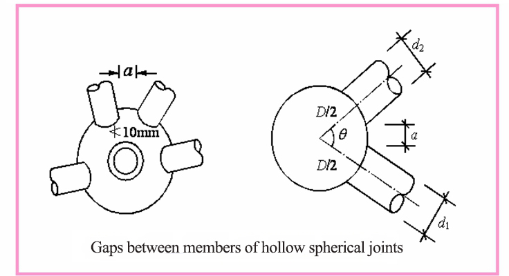
B. The outer diameter D of hollow sphere can be determined according to the requirement of connection structure. For easy welding, the gap between connecting rods on spherical surface should not be less than 10 mm (Fig. 4.5). According to this requirement, the outer diameter D of the hollow sphere can be preliminarily estimated as follows:
C. When the outer diameter of the hollow sphere is greater than 300 mm and the internal force of the rod is large enough to improve the bearing capacity, it can be stiffened in the sphere; when the outer diameter of the hollow sphere is greater than or equal to 500 mm, it should be stiffened in the sphere. The rib plate must be located in the axis plane of the member with the greatest axial force, and its thickness should not be less than the thickness of the spherical wall.
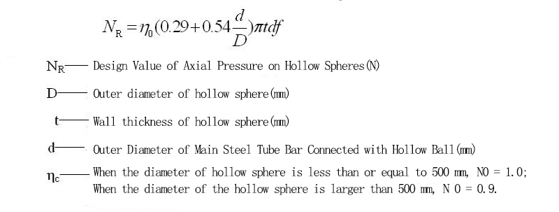
D. When the diameter of the hollow sphere is 120-900mm, the design values of the compressive and tensile bearing capacity of the hollow sphere can be calculated according to the following formula:
D=(d1+2a+d2)/theta
In the formula, theta-intersects the angle (rad) between any two adjacent steel tubular members of spherical joints.
D1, D2 - External Diameter (mm) of Two Steel Pipes with Angle of Theta
E. The wall thickness of hollow sphere should not be less than 4mm, and meet the calculation requirements. The ratio of outer diameter to wall thickness of hollow spheres of latticed shells and double-layer latticed shells should be chosen in the range of D/t=25-45, the ratio of outer diameter to wall thickness of hollow spheres of single-layer latticed shells should be 20-35, the ratio of outer diameter of hollow spheres to outer diameter of main steel tubes should be 2.4-3.0, and the ratio of wall thickness of hollow spheres to wall thickness of main steel tubes should be 1.5-2.0.
F. Pipe end should be grooved and lined at the joint of steel pipe rod and hollow ball. There should be a certain gap between pipe end and hollow ball to be welded through, so as to achieve equal strength between weld and steel pipe. The weld can be calculated according to butt weld. The weld quality should meet the requirements of grade II. Otherwise, it can only be calculated according to the inclined fillet weld.
4.5 Bolted spherical joints
4.5.1 Structure of bolted spherical joints: The joints are joints of steel tubular members joined at joints by high strength bolts on steel spheres with threaded holes. Bolted spherical joints consist of steel balls, high strength bolts, sleeves, fastening screws, taper heads or sealing plates (Fig. 5.4.7), which can be used to connect circular steel tubular members with space grid structures such as grid trusses and double-layer latticed shells.
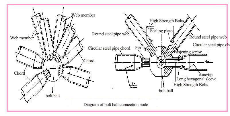
Steel ball should be 45 steel; high strength bolts, pins or fastening screws should be 40Cr, 20MnTiB; sleeve should be Q235B, Q345; taper head and sealing plate should be made of rod type materials.
4.5.2 Steel Ball Size
The stress state of steel balls is very complex, and there is no practical method for strength analysis of steel balls. The diameter of steel balls can be determined according to the joint structure. The size of steel ball depends on the angle of adjacent rods, the diameter of bolts and the length of bolts into the sphere.
4.5.3 Bolt size
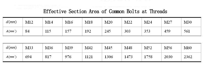
High-strength bolts shall meet the requirements of grade 9.8 or 10.9. The design value of tensile capacity of each high-strength bolt shall be calculated according to the following formula:

In the formula, f refers to the design value of tensile strength of high strength bolts after heat treatment: for grade 10.9, 430N/mm2, for grade 9.8, 385N/mm2;
Ae refers to the effective section area of the bolt. When the bolt is drilled with keyway or drilling hole, Ae should take the smaller value of the two at the thread or keyway or drilling hole.
4.5.4 Sleeve
Usually there is a longitudinal chute, the chute width is generally 1.5 ~ 2 mm larger than the pin diameter. Sometimes the sliding groove can be seated on the bolt, and a screw hole can be arranged on the sleeve.
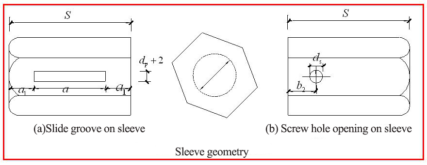
The distance between sleeve end and grooved end (or screw hole end) should make the effective section shear strength not less than that of pin (or screw) and not less than 1.5 times the width of chute or 6 mm. The sleeve end should be kept flat and the inner hole diameter is 1 mm larger than the bolt diameter.

4.5.5 Cone head and sealing plate: When the diameter of round steel tube rod is more than 76mm, cone head connection should be adopted. When the diameter of the round steel tube member is less than 76mm, the sealing plate connection can be adopted. The thickness of the sealing plate should be calculated according to the actual force, and should not be less than 4 mm and 1/5 of the outer diameter of the member. Any section connecting the welding seam and cone head should have the same strength as the connecting steel pipe. The gap between the root of the welding seam can be taken from 2 to 5 according to the wall thickness of the connecting steel pipe.
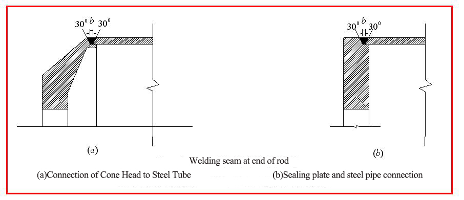
The cone head is an axisymmetric rotating thick shell. The finite element analysis shows that the bearing capacity of the cone head is mainly related to the thickness of the cone roof, the slope of the cone head, the diameter of the connecting rod and the stress concentration of the cone head structure.
4.6 Welded steel plate joints
Welded plate joint can be composed of cross joint plate and cover plate, which is suitable for connection of section steel members. The cross joint plate should be welded by inserting two steel plates with entrance, or by orthogonal welding of three plates.
4.7 Pressure bearing
4.7.1 Single-sided arc pressure support (Figure 4.20), angular displacement is not limited, suitable for medium and small span space trusses.
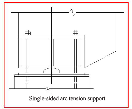
4.7.2 Single-sided arc tension support (fig. 4.21) is suitable for large-span space trusses. In order to better transfer the tension to the support, stiffening ribs should be installed near the anchor bolts bearing the tension to enhance the stiffness of the joints.
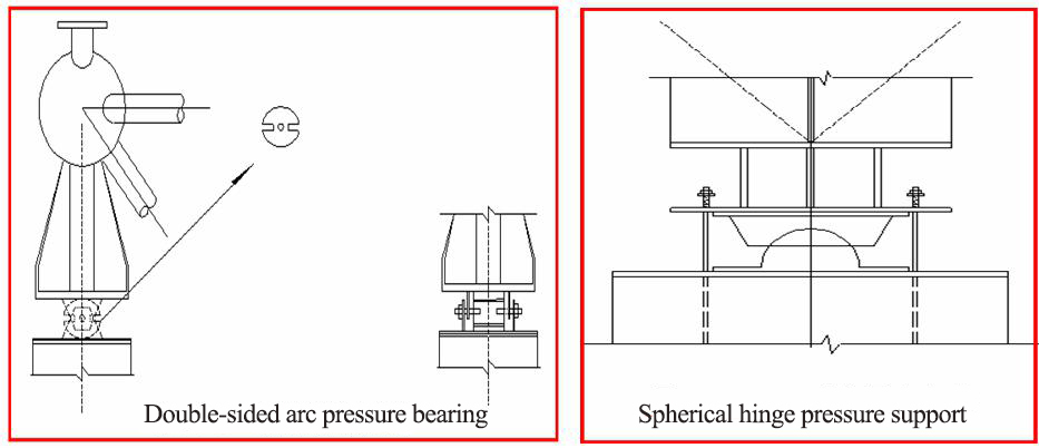
4.7.3Double-sided arc pressure support: (Fig. 4.22) There are arc blocks between the support and the base plate. Both the upper and lower surfaces are cylindrical. The support can rotate and move.
4.7.4 Spherical Joint Pressure Bearing: (Fig. 4.23) It can only rotate but not move. It is suitable for long-span space trusses supported by multiple supports.
4.7.5 Plate Rubber Support: The material of arc support plate should be cast steel, and the one-sided arc support plate can also be processed with thick steel plate. Plate rubber bearing cushion can be made of multi-layer rubber and thin steel plate.
Through the compression and shear deformation of rubber pad, the support can rotate and move. If the restriction is imposed in one direction, the support is one-way lateral displacement type, otherwise it is two-way lateral displacement type.