General process for steel structure box column production
- 17 Jul 2019
- steel structure
Engineering Materials
1. Steel requirements
1.1 All steels must have a quality certificate and should meet the design requirements and related specifications. All materials shall be sampled and sampled for re-inspection according to relevant regulations. The sampling method and test results shall comply with the current national standards; thick steel plates shall be tested for UT according to the regulations to check whether there is any interlayer that does not meet the requirements.
1.2 Steel should have no defects such as peeling, warping, etc. When the surface of the steel has defects such as rust, pitting or scratches, the depth should not be greater than 1/2 of the negative allowable deviation of the thickness of the steel;
1.3 The surface corrosion grade of steel shall comply with the current national standard “Grade grade and derusting grade of steel surface before painting”, Grade C and above specified in GB8923;
1.4 There should be no defects such as delamination and slag inclusion at the edge or fracture of the steel.
1.5 The chemical composition, mechanical properties and other quality requirements of the main steel plates and sections shall be carried out in accordance with the relevant national standards.
2. Welding consumables requirements
2.1 The variety, specifications and performance of welding consumables shall comply with the current national product standards and design requirements;
2.2 The type of welding rod used for manual welding should be compatible with the strength of the base metal. The welding wire and flux used in automatic welding or semi-automatic submerged arc welding should be compatible with the strength of the base metal. All welding rods must have a certificate of conformity. The matching of welding materials with the parent metal should meet the design requirements and the current national industry standards;
2.3 The welding materials used for important steel structure such as first-grade welds shall be sampled and re-inspected. The quantity, method and results of re-inspection shall comply with the current national product standards and design requirements;
2.4 It is strictly forbidden to use the electrode with defects such as peeling off the skin and rusting of the welding core; the flux should be used after baking according to the regulations.
2.5 Welding consumables are shown in the table below
| Welding Method | Material | Welding Number | Welding Location |
|---|---|---|---|
| Manual arc welding | Q345B | E506 | Positioning welding Docking Corner joint |
| Q235B | J422 | ||
| Submerged arc automatic welding | Q345B | H10Mn2+SJ101 H08MnA+HJ431 |
Docking Corner joint |
| Q235B | HO8A+HJ431 | ||
| CO2 gas shielded welding | Q345B | ER50-6 | Positioning welding Docking Corner joint |
| Q235B | ER50-6 |
2.6 The flux should be baked according to the regulations before use: SJ101 should be baked at 300 °C for 2 hours, and HJ431 should be baked at 250 °C for 2 hours.
3. Coating requirements
All coatings must have a product certificate and a package specification for the mixed coating. For materials that have been stored for too long and exceed the service period, samples should be taken for quality inspection. The test items should be carried out according to the requirements of product standards or the requirements of the design department.
3.1 Paint color should be in accordance with the design requirements, in line with the "paint film color standard" GB3181-95 color card number, if necessary, can be used as a model, sealing comparison.
3.2 The paint preparation should be evenly stirred to prevent sedimentation and affect the color. The paint used on the day should be configured on the same day.
3.3 Do not add thinner at will. When the viscosity is too large, it is inconvenient to apply (spray) brush, it can be added in an appropriate amount, but the amount of one additive should not exceed 5%.
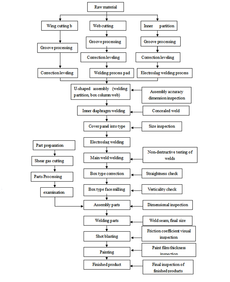
Box type processing technology
1. Box column production process
2. Sheet material
2.1 Groove processing
2.1.1 The processing of the groove is to cut the groove by flame cutting machine, and the surface of the groove after cutting should be cleaned. If other oxides are attached to the edge of the groove, the welding quality will also be affected, so it should be cleaned up;
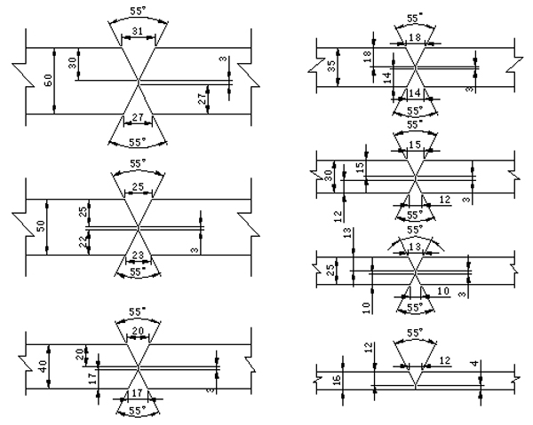
2.1.2 The groove schematic diagram is as follows
2.2 Welding
2.2.1 Before the welding work begins, use wire brush and grinder to remove oxides, rust, paint, oil and other harmful impurities in the range of at least 20mm near the weld;
2.2.2 The positioning welds shall not have defects; the length of the positioning welds shall be 40~50mm, the spacing of the weld bead shall be 150~200mm, and the craters shall be filled. There must be no defects such as cracks, slag inclusions, and welds in the tack weld. If there are defects such as blowholes and cracks on the spot weld, it must be cleaned and re-welded.
2.2.3 Both ends of straight butt joints must be welded with arc-extinguishing plates and arc-extinguishing plates. The arc-ignition and arc-extinguishing plates are important measures to ensure the quality of the welds at both ends. The welds can improve the formal welding through the transition of arc-extinguishing and arc-extinguishing plates. The welding temperature of the zone is to prevent defects such as incomplete penetration and unmelting at both ends of the weld, and also eliminate the crater at both ends of the weld and the crack in the crater. Therefore, the arc should be set at both ends of the weld. The material and thickness of the plate and the arc extinguishing plate shall be the same as the base material. The length of the arc striking plate and the arc extinguishing plate shall be greater than or equal to 80 mm, the width shall be greater than or equal to 60 mm, and the length of the welded joint shall be greater than or equal to 40mm, to ensure the quality of arc ignition and arcing, to prevent crater cracks.
2.2.4 After the steel plate is in place, do the anti-deformation work. Note that the deformation of the side of the first weld is usually larger than the deformation of the side of the post weld. After the reverse deformation, the end of the butt steel plate is fixed. During the welding process, pay attention to the deformation of the steel plate, and turn it over in time to avoid large angular deformation of the steel plate.
2.2.5 For steel plates with a thickness of 36 mm or more, before the butt joint, the welds should be preheated with a baking gun. The preheating temperature is 60-140 ° C (depending on the thickness of the plate), and the preheating range is 100 mm on both sides of the weld.
2.2.6 When the front bottom welding, pay attention to the welding wire to the center of the groove, use the appropriate welding line energy to avoid welding leakage.
2.2.7 Use multi-layer welding, pay attention to the cleaning of the inter-channel slag during the welding process; every weld should be inspected, and the deep groove formed on the edge of the parent metal of the groove should be ground with a grinding wheel until the covered bead can fully melt and penetrate; If it is found that the undercut, slag and other defects must be removed and repaired.
2.2.8 The back side does not need to use carbon arc gouging to clear the root, directly using high current welding to achieve the purpose of full penetration welding.
2.2.9 After the submerged arc welding is completed, the slag and spatter in the weld zone are carefully cleaned. After cooling, the arc striking plate and the arc extinguishing plate are cut and polished.
2.2.10 Submerged arc welding thick plate welding operation should be continuous welding, no intermittent welding is allowed, that is, welding is not allowed after a certain weld is welded for several hours.
2.2.11 When the thickness of the steel plate is 40mm<T ≤ 60mm, after the welding is completed, slow cooling should be carried out, that is, after the welding is completed, the insulation cotton is used for slow cooling.
2.3 Welding inspection
All inspections must be completed after the weld has cooled to room temperature.
2.3.1 After welding, the appearance quality of the weld is checked by 100% appearance quality. Then, the internal quality inspection is carried out by ultrasonic flaw detection. The weld quality inspection standard is Grade 1: The internal defect classification of the joint should conform to the current national standard “Steel Weld Manual Provisions for ultrasonic flaw detection methods and classification of flaw detection results.
2.3.2 Check the dimensional deviation of the butt weld, and the weld size should conform to the current national standard "Structural dimensions of steel structure welds".
| Items | Butt weld size | Illustration and description | |
|---|---|---|---|
| Misalignment (Δ) | t/10 and no more than 2.0 | 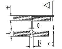 |
|
| Docking gap deviation (A) | 0~1.0 | ||
| Weld seam height (C) | B<20 | 0~3 | |
| B≥20 | 0~4 | ||
| Weld width (B) | B=T+4~8 | ||
3. Sheet blanking
3.1 gas cutting
3.1.1 Receive the materials that have passed the inspection. Check the material, specifications and dimensions of the steel plate in the same way as the processed ticket data. Before the formal cutting, the cutting material of the same type of steel plate should be cut, and the cutting parameters and the smoothness of the gas path of the cutting nozzle should be adjusted.
3.1.2 Lift the steel plate to the gas cutting platform, remove the rust, oil and other impurities on the surface of the cutting area, and adjust the parallelism between the edge of the steel plate and the guide rail to be within 0.5 mm/m.
3.1.3 Adjust the verticality of the cutting gun and the plate surface, set the cutting parameters, and set the amount of kerf compensation (usually one-half of the diameter of the cutting nozzle).
3.1.4 Ignition cutting, remove slag and spatter after cutting, the first part should be strictly inspected during batch cutting, and the cutting can be continued after checking the size.
3.1.5 Cutting and cutting can be used semi-automatic cutting machine, straight cutting machine CNC cutting machine.
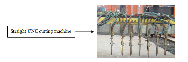
Multi-fire mouth door cutter
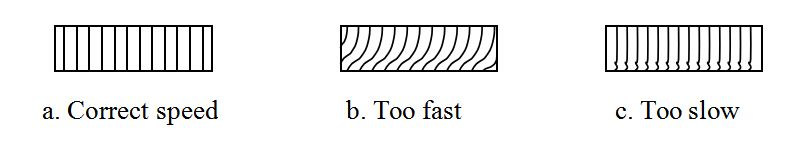
Precautions for flame cutting: The cutting speed should be appropriate. The correct cutting section is shown below:
3.1.6 Inspection: Check the flatness of the cutting surface and the size and shape of the strip should comply with the relevant provisions in Table 1. If there is a cutting defect in the cutting section, it should be repaired. After passing the inspection, mark it as required
| Allowable deviation of gas cutting | |||
|---|---|---|---|
| Item | Allowable deviation(mm) | ||
| Width | ±3.0 | ||
| Length | The drawings are required according to the drawings when required, and ±3.0 when not required. | ||
| Cutting flatness | ≤0.05tand no larger than 2.0 | ||
| Cut depth | 0.3 | ||
| Partial incision depth | ≤1.0 | ||
| Perpendicular to surface | ≤0.5 | ||
| Straightness(△) | ι/3000, and should not be greater than 2.0 | ||
| Web flatness(△) | T≤14 | 1.5 | 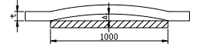 |
| T>14 | 1.0 | ||
| Cutting slag | Clean up | ||
3.1.7 After the completion of the blanking, the production personnel must mark the steel plate specifications and the cutting board number in the middle part of the cutting board after the blanking, and store them according to the classification.
3.1.8 The size of the welding allowance is reserved according to the following process requirements:
When ≤14mm, the welding allowance of 3mm is reserved in the width direction of the web, and the submerged arc welding in the length direction is 0.5mm/m. The electroslag bead has a weld shrinkage of 1 mm each.
When 14<t≤50mm, the welding allowance of 2mm is reserved in the width direction of the web, and the submerged arc welding in the length direction is 0.3mm/m. The electroslag bead has a weld shrinkage of 1 mm each.
When the thickness is >50mm, the welding allowance of 2mm is reserved in the width direction of the web, and the submerged arc welding in the length direction is 0.5mm/m. The electroslag bead has a weld shrinkage of 1 mm each.
A milling volume of 3-5 mm is reserved at the end milling end, and a head amount of 20-30 mm is reserved at the end opening side.
4. Groove processing
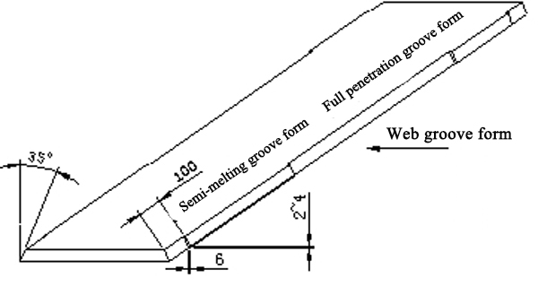
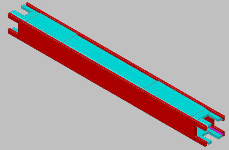
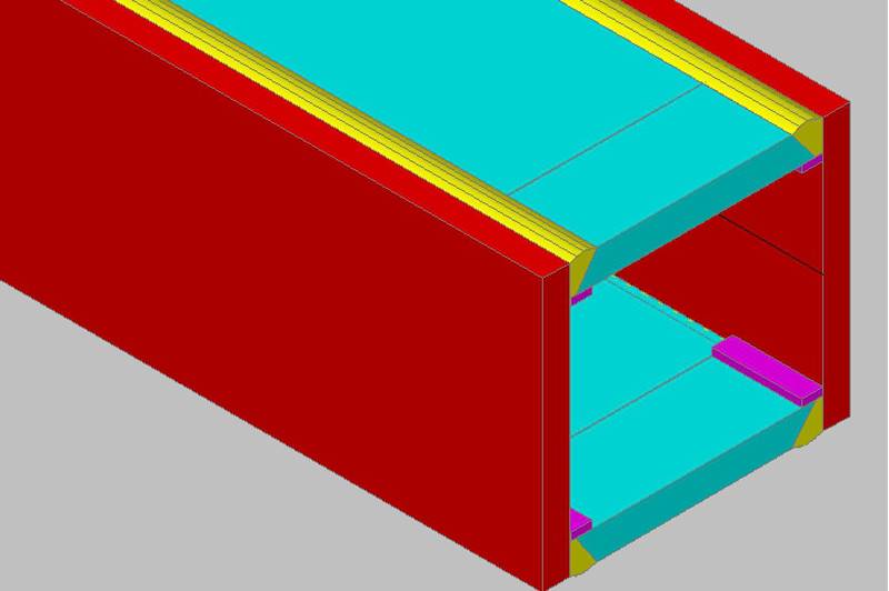
4.1 According to the "Technical Regulations for High-Rise Civil Building Steel Structures" (JGJ99-98), the wing plates and webs of the box-shaped columns are assembled in the form of partial penetration groove. The length of the joint is 600mm above and below the full penetration groove, steel 100mm at both ends of the column is fully penetrated. When the thickness of the flange plate is greater than 30 mm, in order to prevent laminar tearing in the thickness direction, the flange plate also needs to be opened. The thickness of the box column flange plate in the general process is ≤ 30mm. When opening the groove, draw the full penetration and semi-fusion position in advance according to the drawing size. The web groove form is as follows:
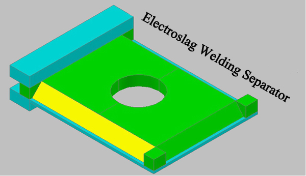
4.2 Box type partition (requires penetration) groove form and electroslag bead assembly requirements: the front side of the front opening is padded for full penetration welding. The electroslag welded separator is assembled as shown in the figure below.
4.3 Groove size and groove surface shall comply with the following table:
| Item | Allowable deviation value:(mm) |
|---|---|
| Width, length | ±1.0 |
| Flatness of cutting surface | ≤0.05t and no more than 2.0 |
| Depth of cutting veins | ≤0.3 |
| Local notch depth | ≤1.0 |
| Groove angle deviation | ±2.5 |
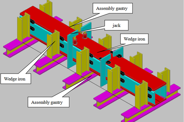
5. Box assembly
5.1 Check the web, wing sign and blanking quality, draw the center line and web position line on the wing and web, and draw the partition and lining position line on the web.
5.2 Assembling the welding lining in the full penetration of the box type web, positioning welding and welding, the first strip line should be executed on the web strip, then the groove is processed, and then the lining installation process is carried out. When installing the board, first install one side liner on the basis of the center line, and then install the other side liner on the basis of the installed liner. The distance between the outer edges of the two liners should be strictly controlled. The positioning weld is welded by gas shielded intermittent weld, the weld length is 60mm and the spacing is 300mm, as shown in the figure below.
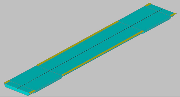
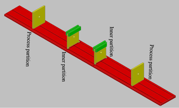
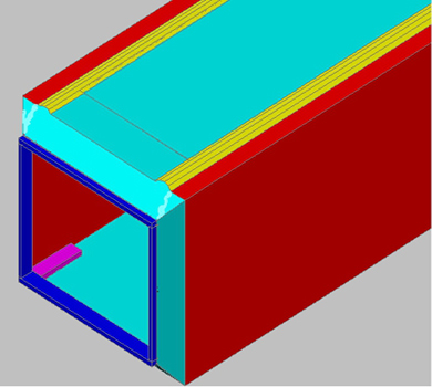
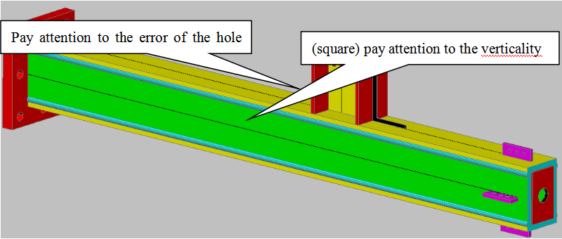
5.3 Place the lined lower wing on the assembly stand on the assembly machine platform, and position the assembled partitions on the lower wing plate (designed for the 1.5 m length of the box without spacers required) Process partition to ensure the size of the box). Check the verticality of the partition. The verticality of the partition and the lower wing shall not exceed 1mm. The requirements are as follows:
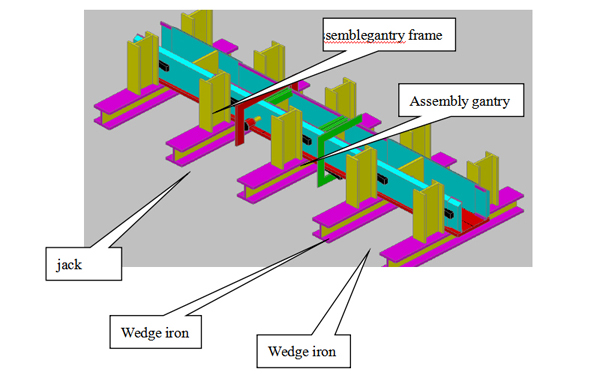
5.4 Use the assembly platform and the self-made gantry, wedge iron and other tools to manually assemble the two sides of the web, so that the partition is aligned with the position on the web. The verticality between the wing and the web should not be greater than b/500 (b For the length of the side); then, the welding between the web and the partition and the weld between the web and the wing, if the strength of the wedge iron is not enough, the jack can be used for pressing, as shown in the following schematic diagram:
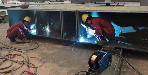
5.5 Hang the U-shaped box to the welding platform, and perform full penetration welding on the weld between the partition and the web and the lower flange by CO2 gas shielded welding. After the welding is completed, the weld is to be cooled. UT detection.
5.6 The process partition is welded on three sides, but the welding angle should not be too large, and intermittent welding can also be carried out.
5.7 For the concealed partition welds in the box type, it must be inspected and photographed to record the other side panels.
5.8 Re-hook the U-shaped box that has been welded and tested to the assembly platform. Use the self-made gantry and wedge iron to press the upper wing. If the strength of the wedge iron is not enough, the jack can be used for pressing. The gap between the internal slag electroslag welding shall not exceed 1mm, and the verticality between the web and the wing shall not exceed 1mm.
5.9 Clean up, correct, and inspect the assembled box size to ensure that the specifications are met. The assembly quality of the box column should meet the requirements of the following table:
| Assembly of Box Members | ||||
|---|---|---|---|---|
| Inspection Item | Allowable Deviation(mm) | Testing Method | Illustration | |
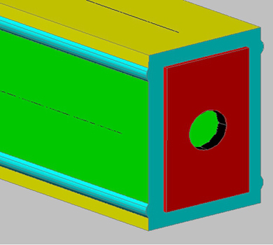
| Horizontal diaphragm electroslag welding hole deviation | ±2.0 | Check with steel ruler | 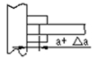 |
|
| Inner diaphragm assembly gap deviation | 1.0 | Check with a square ruler | 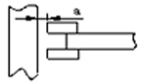 |
|
| Root groove opening with pad gap deviation | ±2.0 | Check with steel ruler | 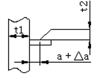 |
|
| Internal diaphragm tilt deviation | 2.0 | Check with a square ruler | 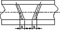 |
|
| Internal diaphragm position deviation | 2.0 | Check with steel ruler | 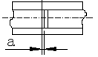 |
|
| Flange slope | b≤400 | 3.0 | Check with a square ruler | 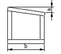 |
| b>400 | 5.0 | Check with a square ruler | ||
| Joint site | B/100≤1.5 | Check with a square ruler | ||
| Column section size deviation | h≤400 | ±2.0 | Check with steel ruler | 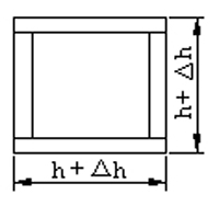 |
| 400<h<800 | ±h/200 | Check with steel ruler | ||
| h≥800 | ±4.0 | Check with steel ruler | ||
6. Box welding
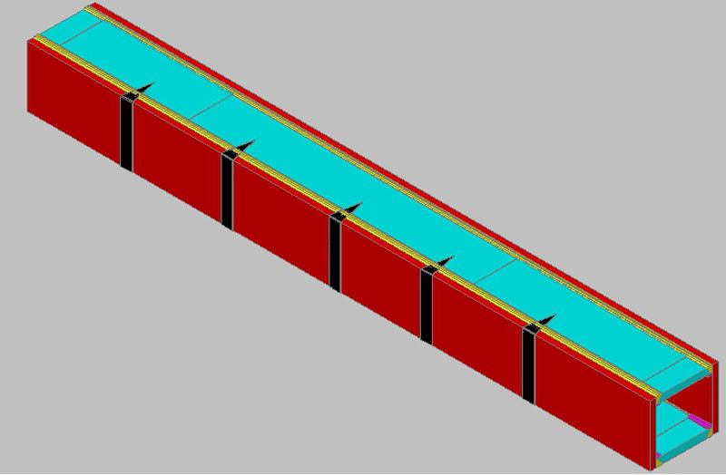
The submerged arc welding part of the box column is four outer longitudinal joints, and the joint part of the joint is 600mm for full penetration welding, and the partition at the joint is equipped with electroslag weld.
6.1 Preparation before welding
6.1.1 Check the bending degree of the box type column in the longitudinal direction, and decide which side to weld first according to the deformation condition.
6.1.2 Use a wire brush (wire brush on the sander) to remove rust, oil and other debris within a range of at least 30mm near the weld.
6.1.3 Welded and extinguished arc plate, the arc-extinguishing plate should be the same or equal to the material of the base material, the length should be greater than 150mm, the width should be greater than 80mm, and the length of the weld should be no less than 80mm to ensure the quality of the arc and arc. Crack in the crater.
6.2 Primer welding
First, the base is made of CO2 gas shielded welding, and the thickness of the base is not less than 10mm, so that it can withstand the tensile stress caused by shrinkage deformation. After the bottom welding is completed, the weld is polished to remove debris such as welding slag and splash.
6.3 Electroslag welding
6.3.1 After the bottom welding is completed, the residual dirt in the electroslag welding hole is removed for electroslag welding.
6.3.2 The inner baffle adopts three-sided CO2 gas shielded welding and one side electroslag welding;
6.3.3 After the welding starts, the arc must be fully burned. The welding voltage should be 2-4V higher than the normal voltage during the start-up. During the welding process, the welding slag pool is formed and then drops to the normal welding voltage.
6.3.4 When the arc is closed, the welding current and voltage can be gradually reduced to prevent shrinkage cracking.
6.3.5 After the welding is completed, the weld slag should be cleaned and cleaned by CO2 gas shielded welding to the bottom welding and smoothed.
6.4 Box type body welding
After the electroslag welding is completed and the slag is cleaned together with the bottom welding, the main weld bead is fully automated submerged arc welded.
6.4.1 When submerged arc welding, the four longitudinal joints follow the same direction of the two welds on the same side, and the same standard welding principle is adopted to reduce the welding deformation of the components.
6.4.2 Because the full penetration weld bevel at the joint is inconsistent with the semi-melting groove, it can be repaired to the same level as the semi-penetrated weld and then filled and welded, and always consistent to create conditions for the cover, cover bead The non-broken arc should be welded once and continuously. If the weld bead is too wide, it can be divided into sections.
6.4.3 After the welding is completed, the defects such as the weld bead and the vent hole are cleaned, so that the arc-extinguishing plate is cut off after cooling to normal temperature, and the smoothing is smoothed.
6.4.4 The welding of the main weld is carefully done in the welding record, and the welder's mark is placed after the welding is completed.
6.4.5 Check the box size, shape, and weld size tolerances as shown in the following table:
| Weld Connect of Box Type Column | ||||
|---|---|---|---|---|
| Test Items | Allowable Deviation mm | Testing Method | Illustration | |
| Solder angle deviation | d≤6mm | 0—1.5 | Angle check | 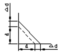 |
| d>6 | 0—3 | |||
| Fillet weld height | d≤6 | 0—1.5 | Angle check | 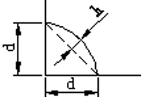 |
| d>6 | 0—3 | |||
| Butt weld height | b<15 | 0.5~3 | Ruler inspection | 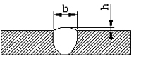 |
| 15≤b<20 | 0.5~4 | |||
| T-joint weld seam height | t≤40 a=t/4 | 0~5 | Angle check | 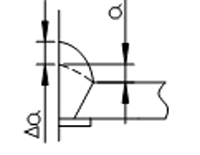 |
| t>40 a=10mm | 0~5 | Angle check | ||
| Undercut | e≤t/20 and e≤0.5 | Welding square examination | 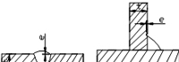 |
|
| Weld width deviation | ≤5mm in any 150mm range | Angle check | 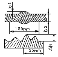 |
|
| Weld surface height | ≤2.5mm in any 25mm range | Angle check | ||
| Surface vent | For fully penetrated joints, the length of the partially welded joint welds is not more than 1m, no more than 2, and the weld length is more than 1m per meter. | 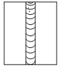 |
||
| Submerged arc welding full penetration weld 100% UT inspection | Implementation of "manual ultrasonic inspection method for steel structure welds and classification of flaw detection results" GB11345-89 | |||
| Electroslag welding seam 100% UT flaw detection | ||||
7. Box type body flame correction
7.1 The box column is welded. After it is completely cooled, it will be bent and deformed. It should be corrected. The box body is generally flame corrected. When the flame is corrected, the temperature value should be controlled between 750 and 900 °C. The heating correction of the same part should not exceed 2 times. After the correction, it should be slowly cooled. The low alloy steel should not be quenched with water.
7.2 Flame correction is the use of flame to locally heat the steel, so that the heating part is compressed and plastically deformed due to expansion, so that the longer metal fiber is cooled and shortened.
7.3 The position of the flame heating should be selected in the longer part of the metal fiber. The heating form is generally available, local point heating and triangular heating. The point heating position is the central part of the local convex deformation, and the triangular heating position and shape are as shown below:
7.4 The height of the triangle heating and the width of the bottom are 1\5~2\3 of the height of the profile. Different heating heat can be used to obtain different correction ability. When the low carbon steel member is used for flame correction, the heating temperature of 600~800 °C is often used.
Low alloy steel heating temperature is 750~900 °C, slow cooling, no water cooling.
8. End milling
8.1 Check the main part of the box type column for the qualified mark. Place the box type main body on the workpiece support of the end mill, so that the column bus bar is perpendicular to the end face milling cutting plane, and then clamp the box column main body.
8.2 The end face of the box type is machined according to the size requirement, the surface roughness is required to be 0.03mm, and the flatness is required to be 0.3. The allowable deviation of the perpendicularity is not more than 1.5H/1000, and H is the length of the section.
8.3 When the lower column is made, the top end needs to be milled. When the upper column is made, the bottom of the column needs to be welded to the ground:
9. Box type column and component assembly welding
9.1 After checking the end milled components and parts with the drawings, the steel stamps shall be marked on the adjacent sides of the end 500mm from the end. The stamp shall be clear and clear. It is not allowed to have a delineation. If there is an error in the stamp number, the original stamp number must be removed and the stamp should be re-printed. The steel stamp is circled with a white paint stroke.
9.2 Draw the center line of the box-type body, and then use the top-end milling surface of the box-type column as the reference. According to the drawing size, the end plate and the ox leg are attached, the positioning welding is firm, and the inspection personnel are inspected. Only after the qualification is passed, the welding construction is allowed.
9.3 Welding construction, welding is completed according to the drawings and process requirements. Defects such as splashes and welds are removed after the welding is completed.
9.4 Inspection: Inspect according to the drawings and process requirements. After passing the test, transfer to the following procedures.
The tolerances of the assembly of the peripheral components of the 9.5 box column are shown in the following table.
| Items | Allowable deviation(mm) | Illustration | Measuringtool | |
|---|---|---|---|---|
| Height of column H | ±3.0 | 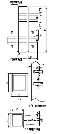 |
Steel ruler | |
| Depth of sectionh(b) | Junction | ±3.0 | ||
| Non-joined | ±4.0 | |||
| The distance from the milling plane to the first mounting hole | ±1.0 | |||
| Column bending | >H/1500 and no more than 5.0 | Pull wire, steel ruler | ||
| Cow leg hole to column axis distance L2 | >±3.0 | Steel ruler | ||
| Column twist | h/250 and no more than 5.0 | Pull wire, wire hammer, steel ruler | ||
| Warping, twisting, side deviation of the support△ | L2≤1000 | 2.0 | ||
| L2>1000 | 3.0 | |||
| Length deviation of the support | ±3.0 | |||
| Angle deviation of skewed support | 4.0 | 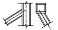 |
Steel ruler Feeler | |
| Column end perpendicularity | 1.5h/1000 | 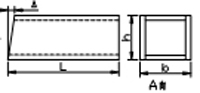 |
Square ruler Feeler | |
| Diagonal difference between box-type column joints | 3.0 | 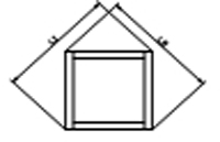 |
Steel ruler | |
| Column foot plate unevenness | 5.0 | 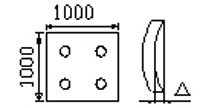 |
Square ruler Feeler | |
| The distance between the column bolt holes and the axis of the column a | 3.0 | 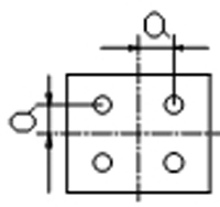 |
Steel ruler | |
10. Rust removal and painting
10.1 The shot blasting and painting equipment used by our company is as follows
| Shot blasting | Shot blasting machine | XQB12HE(10) | set |
| Spray paint | Airless spraying machine | GPQ6C | set |
10.2 The cleanliness of the outer surface of the steel structure requires that the degree of derusting should reach the level of Sa2.5 of GB8923-88. On-site repainting should be carried out by pneumatic or electric tools to achieve ST3 level.
10.3 The edges of the components must be rounded to ensure the paint adhesion of the edges.
10.4 After the steel derusting has passed the inspection, the anti-rust primer should be sprayed within six hours.
10.5 When painting, it should be noted that no paint or oil stains are allowed in the connection range of high-strength bolts. The contact surface with concrete or parts of the embedded parts is not painted, and the welding parts of the site are not painted.
The schematic diagram of the painting construction is as follows:
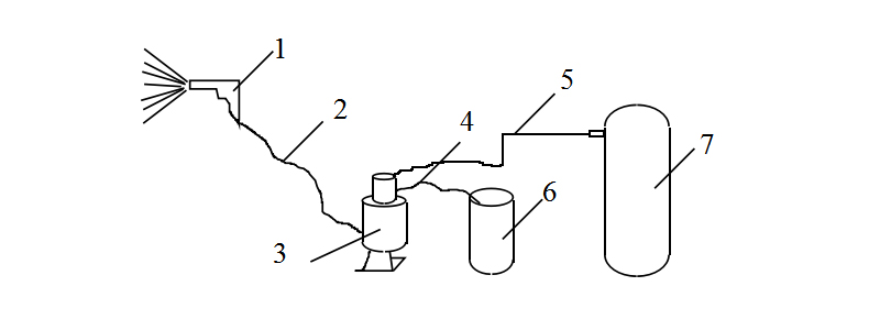
①spray gun ②high pressure paint delivery pipe ③air pump ④paint suction hose ⑤air pipe ⑥paint ⑦compressed air storage bucket
10.6 Using a paint dry film electronic thickness gauge, each component is tested at 5 locations, and the value of each location is the average of the dry film thickness of the coatings at 3 50 mm apart.
10.7 Painting Inspection Pay special attention to whether there is any damage to the paint film caused by collision, bump and deformation caused by handling.
10.8 touch up paint:
10.8.1 Pre-primed steel If the surface is damaged by rolling, cutting, welding or installation, so that the paint is damaged or rusted, it must be cleaned with a bead or electric tool before repainting.
10.8.2 After the paint is applied, if the paint film is found to have cracks, wrinkles, brush lines, sag, powdering, loss of light, etc., the paint film should be scraped off and sanded and repainted.
After painting, if there are any phenomena such as foaming, cracking holes, peeling rust or pinholes, the paint film should be scraped off and surface treated, then the gap layer should be applied according to the regulations to make up the paint.
The touch-up material must use the same properties as the original construction.
11. Packaging and transportation of components
After the finished product is put into storage, it should be packaged according to the requirements. Temporary stacking should be piled up as far as possible in a place where there is no water. The stacking inside and outside the plant must be neat, reasonable, and clearly marked. If necessary, prevent rain. In the case of fog treatment, the butt joints should be protected. Prepare for shipping in the order of installation.