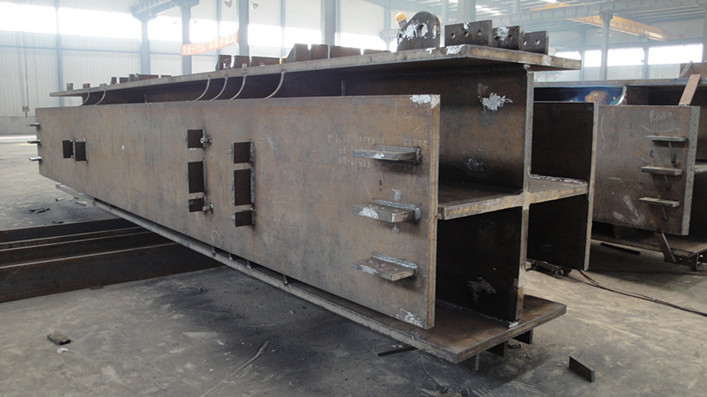
General Production Way of Cross-shaped Column
- 30 Sep 2019
- steel structure
1. Production Process
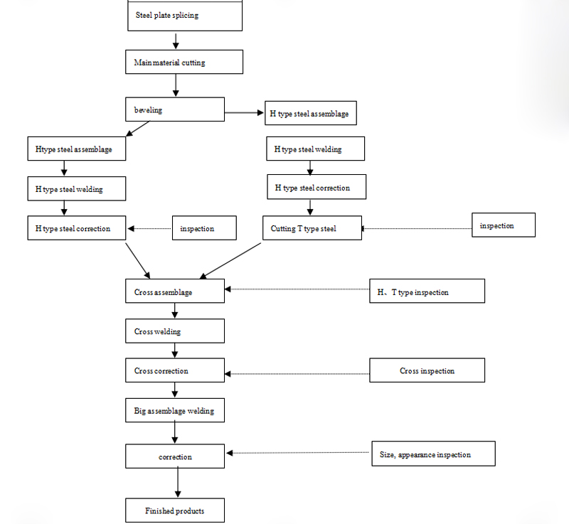
2. Laying-off
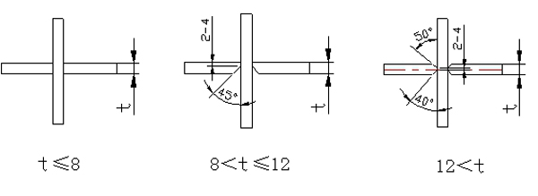
2.1 The groove form of the four main welds of the steel structure cross-shaped column is processed according to the following requirements:
2.1.1 When drawings and processes are required, they are processed according to requirements.
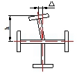
2.1.2 When not required, they are processed according to the following diagram.
2.2 Technical requirements
After the laying-off is completed, the size and shape are inspected according to the requirements, and the precision of the overall assembly of the cross-shaped column is ensured by strict control of the deviation. The welding surface should be carefully inspected to remove foreign matter such as rust, burrs, oxide scales and others within 30~50mm on each side of the clean weld edge; the construction personnel must mark and classify the members after the laying-off.
2.3 Cutting plate identification
After the laying-off has passed the inspection, in the center of the cutting plate, marking the the number,specification, size and engineering name of the cutting plate with a white paint pen.
3. H-type steel assemblage
3.1 The H-type steel assembly is carried out on the H-type steel automatic assemblage machine; the positioning welding adopts gas shielded welding, and the positioning welding spot length is 40 mm to 60 mm, and the spacing is 250 to 300 mm.
3.2 T-type steel assemblage
In order to reduce the welding deformation of T-type steel, firstly, H-type steel is assembled on the automatic assemblage machine, and the gas shielded welding is adopted for the positioning welding.
3.3 The locks of the assembled H-type steel and T-type steel (composed H-type steel) are automatically completed by the assembly line composed of the sawing machine, the three-dimensional drilling and the locking machine;The wearing of the rib holes are completed by the three-dimensional drilling.
3.4 Cross-shaped column assemblage positioning welding: Before welding, the welding surface should be carefully inspected to eliminate oxides and other debris. For the installation of T-type steel, it should be assembled according to the requirements of the drawings, and the scribbling should be used to ensure the accuracy of the assemblage; The positioning welding is performed by CO2 gas shielded welding and the height of the positioning welding feet should not be greater than 2/3 of the height of the designed weld bead feet; the length of the positioning weld is 50mm and the spacing of the weld bead is 250mm. The positioning welding shall not have defects such as cracks, slag inclusions, and welds; pay attention to the length of the positioning weld to ensure sufficient strength. Check the relative position of the rib holes. While ensuring the position of the rib holes, leave the 3-5mm amount of end milling at the top and bottom of the column.
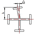
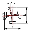
3.5 A simple tire frame can be used when the cross-shaped column is assembled. The schematic diagram of the tire frame is as follows:
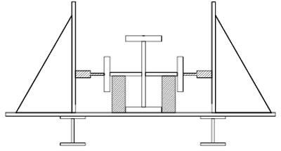
Cross-shaped column assemblage simple tire frame
3.6 Process requirements of Cross-shaped column welding and assemblage
Cross-shaped column pairing and assembly allowable deviation
| Item | Process requirements of welding and assemblage | |
|---|---|---|
| 1 | Arc bruising is not allowed, Spot welding bite edge≤1mm | |
| 2 | The joint between the flange and the web plate should be staggered by more than 200mm to avoid stress concentration at the intersection of the weld bead | |
| 3 | The installation gap between flange plate and web plate Δ≤0.75mm | |
| Item | H-type steel assemblage allowable deviation(mm) | |
| Length(L) | ±3.0 | 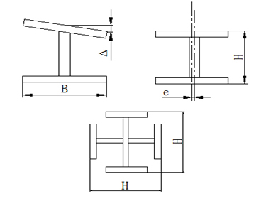 |
| Height(H) | ±2.0 | |
| perpendicularity(Δ) | ≤B/100and no longer than 2.0 | |
| off-centering(e) | 2.0 | |
3.7 After the assemblage of components are completed, marking the component number at the 300-500mm end of the web plate of the components by a white paint pen.If there is area requirements, please mark the area code.As for the components with same component number should mark the serial number, and separately noted by “∽”.
3.8 Inspection requirements after components assemblage
According to the drawings and process requirements, strictly check whether the pair size is correct. The deviation requirements after the cross-shaped column assemblage are as follows:
Cross-shaped column assemblage deviation
| Item | Allowable deviation(mm) | Legend | Measurements tools | |
|---|---|---|---|---|
| T-type connection gap | t<16 | 1.0 |  |
Feeler gauge |
| t≥16 | 2.0 | |||
| Butt joint bottom plate misalignment | t≤16 | 1.5 |  |
Angle ruler |
| 16<t<30 | t/10 | |||
| t≥30 | 3.0 | |||
| Butt joint gap deviation | Manual arc welding | +4.0 | 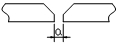 |
Steel ruler, feeler gauge |
| Automatic submerged arc welding Gas shielded welding |
+1.0 | |||
| Straightness accuracy deviation of butt joint | 2.0 |  |
Steel ruler | |
| Root opening gap deviation (back lining plate) |
±2.0 |  |
Steel ruler, angle ruler | |
| End deviation of welding assemblage components | 3.0 | 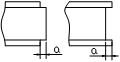 |
ruler | |
| Connection plate, stiffening rib space and location deviation | 2.0 |  |
Suspension wire, steel ruler | |
| Misalignment amount between baffle and beam flange | t1≥t2 and t1≤20 | t2/2 | 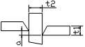 |
Steel ruler、angle ruler |
| t1≥t2 and t1>20 | 4.0 | |||
| t1<t2 and t1≤20 | t1/4 | |||
| t1<t2 and t1>20 | 5.0 | |||
| Slope deviation of stiffening plate or baffle | 2.0 | 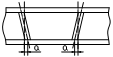 |
Suspension wire, steel ruler | |
| Cross-section height(h) | h≤2000 | ±2.0 |  |
Steel ruler |
| h>2000 | ±3.0 | |||
| Cross-section width b | ±2.0 | |||
| Perpendicularity of two web plates Δ | Connection parts | h/300 And no longer than 1.5 |
 |
Square ruler |
| Other parts | h/200 And no longer than 2.5 |
|||
| Web plate center offset e | Joint parts | 1.5 |  |
Steel ruler |
| Other parts | 2.0 | |||
| Local flatness of web plate f/m2 | Web plate t<14 | 3.0 |  |
1m steel square ruler feeler gauge |
| Web plate t≥14 | 2.0 | |||
4.H-type steel welding
4.1 H-type steel welding method and welding sequence:
H-type steel welding and T-type steel welding (has been formed into H-type steel) adopts gate type submerged arc automatic welding and welding at the ship-shaped welding position. During welding, simple tooling can be made and the flange plate can be clamped to reduce deformation.
4.2 Welding preparation:
4.2.1 Check the deformation degree of the H-type steel in the longitudinal direction, and decide which side to weld firstly according to the deformation condition. Usually, the deformation of the first welding bead is the largest.
4.2.2 The flux adopts flux HJ431, and should be dried at 250 ° C for 2 h; the welding wire is H08A, φ 4 mm.
4.2.3 When repairing defects, the repair welding can adopt gas shielded welding or acid electrode (optional J422).
4.2.4 Use a wire brush to remove debris such as rust, oil and others within a distance of at least 20 mm near the weld.
4.2.5 In order to ensure the welding quality of the leading arcing end and the finished arcing end, the arc striking plate and the lead plate are welded in the two end of components. The material, thickness and groove form of striking plate and the lead plate should be same with the base material. The length of the striking plate and the lead plate should be greater than or equal to 150mm, the width should be greater than or equal to 100mm, and the length of the weld lead should be greater than or equal to 80mm to ensure the quality of the lead arc and finished arc to prevent crater cracks.
4.3 Correction Process
4.3.1 H-type steel correction is carried out on a straightening machine. H-type steel (sections or plate thicknesses beyond the machine correction range) that cannot be corrected on the straightening machine should adopt flame-correction, and the correction temperature is at 800-900 °C. There must be no over-burning.
4.3.2 The surface of the corrected steel plate should be free of obvious depressions or damage, and the scratch depth should not exceed 0.5mm.
4.3.3 Allowable deviation of corrected H-type steel
Allowable deviation of welding H-type steel
| Item | Allowable deviation(mm) | Diagram | |
|---|---|---|---|
| Section Height | h<500 | ±2.0 | 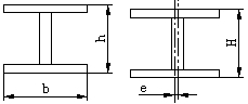 |
| Section width(b) | ±3.0 | ||
| Web plate center offset(e) | 2.0 | ||
| Flange plate perpendicularity(Δ) | b/100, and no more than 3.0 | 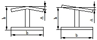 |
|
| Tortuosity sagittal height | L/1000 and no more than 5.0 | 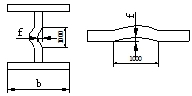 |
|
| Tortuosity | h/250 and no more than 5.0 | ||
| Local flatness of web plate(f) | t(plate thickness)<14 | 3.0 | |
| t(plate thickness)≥14 | 2.0 | ||
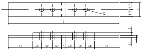
4.4 Drilling Process
4.4.1 Drilling adopts the following equipment on AMADA production line: CNC three-dimensional drilling machine, plane drilling machine, rocker drill and others.
4.4.2 When numerically drilling in a large numbers, the first piece should be carefully inspected before it can continue.
4.4.3 Allowable deviation of ordinary bolt.
Allowable deviation of holes (C grade)
| Item | Allowable deviation(mm) | |||
|---|---|---|---|---|
| Diameter of holes | 0~+1.0 | |||
| roundness | 2.0 | |||
| perpendicularity | 0.3t and no more than 2.0 | |||
| Allowable deviation of bolt hole distance | ||||
| The space between any 2 holes in the same group | ≤500 | 501~1200 | 1201~3000 | >3000 |
| ±1.0 | ±1.5 | - | - | |
| Distance between end holes of two adjacent groups | ≤500 | 501~1200 | 1201~3000 | >3000 |
| ±1.5 | ±2.0 | ±2.5 | ±3.0 | |
| Notes:When the allowable deviation of the bolt hole exceeds the above requirements, it shall not be packed with steel blocks, and the welding rod matching the material of the base material may be used to repair welding and then re-make the hole. | ||||
4.4.4 Allowable deviation of refined bolt holes (A and B grades):
| Bolt nominal diameter, screw hole diameter | Allowable deviation of bolt nominal diameter | Allowable deviation of screw hole diameter |
|---|---|---|
| 10-18 | -0.18~0 | 0~+0.18 |
| 18-30 | -0.21~0 | 0~+0.21 |
| 30-50 | -0.25~0 | 0~+0.25 |
4.4.5 The burr should be cleaned after the drilling is completed.
4.5 T-type steel part
The H-type steel is divided into T-type steel after correction and hole making. The difficulty of this part is that the T-type steel has a large deformation after the split and is not easy to correct.
4.5.1 Place the H-type steel on the tire frame flatly, play the center line, and draw it clearly with a stone pen. See the Rules for the laying-off.
4.5.2 Arrange the semi-automatic cutting machine along the center line to adjust the flame (see the rules for the laying-off). And go back and forth to test whether the walking trajectory is consistent with the center line.
4.5.3 At the time of splitting, a length of 200~300mm is reserved at both ends of the H-type steel without division.
4.5.4 After splitting and cooling, separate the two ends. Use a grinder to trim the groove.
4.6 Friction surface quality requirements
4.6.1 Friction surface processing
(1)The friction surface is processed by shot blasting and sand blasting, and the surface is with metallic luster after being treated. The anti-slip coefficient of the friction surface should meet the design requirements. When the design is not required, the derusting level should achieve Sa2.5.
(2)The friction surface should be flat and free of oil, and there are no flashes or burrs on the edges of the holes and plates.
4.6.2 Anti-slip coefficient test:
(1)The anti-slip coefficient test is carried out according to the steel structure production batch, three sets of test pieces are produced in each batch, and another three sets of test pieces are prepared for re-inspection during installation.
(2)The test piece and the representative steel structure member are made of the same material, made in the same batch, treated by the same friction surface and have the same surface state, and will be handed over at the same time.
(3)The test piece form is shown in the figure. The thickness of the test piece t1 and t2 are determined according to the thickness of the representative plate in the project. The width b is taken as specified in Table 8. The test piece surface should be flat, no oil. There are no flashes or burrs on the edge of the holes and plates.
| The width value of the anti-slip test piece | ||||||
|---|---|---|---|---|---|---|
| Bolt diameter d | 16 | 20 | 22 | 24 | 27 | 30 |
| Width of test pieces b(mm) | 100 | 100 | 105 | 110 | 120 | 120 |
4.7 Cross-shaped column welding
The cross-shaped weld of the cross-shaped column is welded by gate-type submerged arc welding, lengthened contact nozzle and ship-shaped welding position welding. Welding parameters see the Welding Process Card.
4.7.1According to the structural form of the cross-shaped column weld, in order to control the deformation during the welding process, the welding sequence is to be followed, and the welding sequence is as follows:
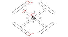
4.7.2 After cleaning the weld, the whole continuous submerged arc weld is welded, and the weld bead is welded in two layers. After each layer is welded, the weld slag and weld defects between the layers should be strictly cleaned, and the defects should be immediately grind or remove by air gouging and the repair welding.
4.7.3 The interlayer temperature is controlled within the range of 150~200°C. If it exceeds 200°C, the welding should be stopped. After cooling for 10-20 minutes, the welding should be carried out to reduce the deformation. The deformation of the cross-shaped column should be checked at any time during the welding process, and the deformation of cross-shaped welding should be adjust by the following welding.
4.7.4 Clean, cool, cut off the lead plate and the arcing plate, and polish.
4.7.5 If it is found that the cross-shaped column is deformed, it should be corrected by flame. The flame temperature should be controlled between 750 and 900 °C. The heating correction of the same part should not exceed 2 times. After correction, it should be slowly cooled.
4.7.6 For the detected out-of-tolerance defects, use carbon arc gouging to remove and polish. Then use gas shielded welding or manual arc welding to clean and polish; the detailed process requirements of welding repair are detailed in the requirements of the weld rework process in the General Process for Box-Type Members Manufacturing.
4.8 Large Assemblage Process
According to the component number, and confirm with the drawings to make sure it is correct, the steel stamps are placed on the adjacent two flange plates at a distance of 500 mm from the end. The stamp should be clear. The steel stamp is surrounded by a white paint pen.
Based on the top surface after end milling, scribe and assemble accessories such as ox legs and ribs. After inspection, the welding can be allowed. Finish the welding according to the drawings. After the welding is completed, the welding defects such as welding slag, splash, pores and welding should be removed.
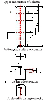
4.9 Finished products inspection
The size and cross-section requirements of finished welding cross-shaped column r are shown in the table below.It should be marked after passing the inspection.
| Item | Allowable(mm) | legend | Measurements tools | |
|---|---|---|---|---|
| Height of column H | ±3.0 |
|
Steel ruler | |
| Cross-section height h(b) | Connection part | ±2.0 | ||
| Non-connection part | ±3.0 | |||
| The distance from the milling plane to the first installation hole | ±1.0 | |||
| Distance from the upper surface of the ox leg to the bottom of the columnL1 Distance between the upper surface of the two ox legs L4 |
±2.0 | |||
| Vertical curvature of column | H/1500 and no more than 5.0 | Steel wire steel ruler | ||
| Warping, twisting, side deviation of the ox leg Δ | L2≤1000 | 2.0 | Steel wire Line hammer Steel ruler |
|
| L2>1000 | 3.0 | |||
| Length deviation of ox leg | ±3.0 | |||
| Distance between hole of ox leg to the column axisL2 | ±3.0 | |||
| End milling plane Surface roughness |
0.03mm | inspection template | ||
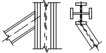
| Angle deviation of oblique ox leg | 2.0 |
|
angular template feeler gauge |
|
| Verticality of two web plates Δ | Connection part | h/300, and no more than 1.5 |
|
Square ruler |
| Other parts | h/200, and no more than 2.5 | |||
| Column twisting a | h/250, and no more than 4.0 |
|
Steel wire Line hammer Steel ruler |
|
| Web plate offset e | Connection part | 1.5 |  |
Steel ruler |
| Other parts | 2.0 | |||
| Column end surface Verticality |
End milling plane | h/800, and no more than 1.0 | 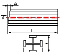 |
Square ruler Feeler gauge |
| Non-end milling plane | h/400, and no more than 2.0 | |||
| Web plate local flatness f/m2 | Web plate t<14 | 3.0 | 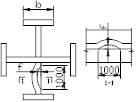 |
1msteel square ruler Feeler gauge |
| Web plate t≥14 | 2.0 | |||
| Flange plate verticality Δ | Connection parts | b/100, and no more than 1.5 | 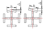 |
Square ruler |
| Other parts | b/100, and no more than 3.0 | |||
| Column foot plate flatness | 3.0 |  |
Square ruler Feeler gauge |
|
| Distance of the column foot bolt hole to the column axis a | 1.5 |  |
Steel ruler | |
4.10 Cross-shaped column stud welding
4.10.1 The studs shall be subjected to the welding procedure evaluation before welding. The stud welding process shall be determined according to the welding procedure qualification. According to the specification, the bending test shall be carried out after the stud welding, and the inspection quantity shall not be less than 1%; when hammering the welding head, and make it 30°bending from the original axis, then the weld and heat affected zone must not have visible cracks.
4.10.2 The welding of the studs is carried out by a stud welding machine, and the diameter of the studs is selected according to the design requirements.
For details of the specific requirements and processes, see General Technical Conditions for Stud Welding.
4.11 column-shaped column shot blasting and painting
4.11.1 For the components to be welded in the factory and the parts to be welded on site, the shot- blasting must be carried on as required before leaving the factory;
4.11.2 Shot blasting must reach Sa2.5 level, and its quality grade meets the requirements of the current national standard “Corrosion grade and derusting grade of steel surface before painting”.
4.11.3 The specific process requirements for shot blasting and painting are detailed in the relevant requirements of 3JS/WI/JS-TG-009 in General Procedure for Derusting and painting.
4.12 Identification of the finished products
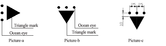
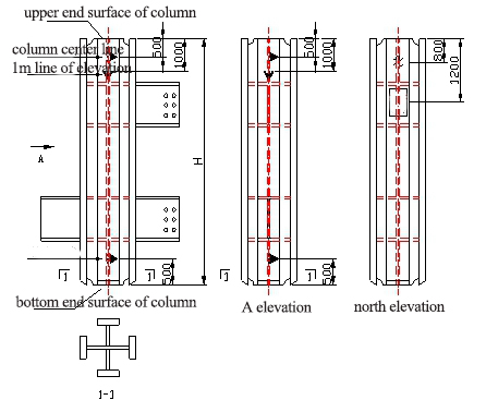
4.12.1 On the two adjacent flange plates of the cross-shaped column, mark the center line of the column at 500 mm from the upper end surface of the column and the lower end surface of the column (the center line mark symbol is shown in Figure a), and mark the line of elevation at 1000 mm from the upper end surface of the column. The line of elevation marker symbol is shown in Figure b). See Figure c for details.
4.12.2 The triangle is marked as an equilateral triangle with a side length of 50 mm and its internal fill color is white.
4.12.3 The relative positional relationship between the triangle mark and the ocean eye in center line mark and elevation line mark is as follows:
4.12.4 On the north elevation of the column, the word "North" is sprayed 800mm from the upper end of the column. The font is Song, and the size is 80x80mm.
4.12.5 On the north elevation flange plate of the column, spray the project name and component number at 1200mm from the upper end surface of the column. The font is Song, the word spacing is 25mm, and the size is 60x60mm.
4.12.6 All words are white in color.
4.13 Product stacking
Product stacking should be piled up as far as possible in a place where there is flat and no water accumulation. The stacking inside and outside the factory must be neat, reasonable, and clearly marked. If necessary, prevent rain and fog, and the docking surface should be protected. For details, please refer to the “Procedures for Product Protection Management”.
4.14 Product shipment
After passing the product inspection, the qualified label should be affixed and the warehousing procedure should be completed. The components that finished the warehousing procedures can be shipped.