Installation Method and Technical Measures of Steel Structure on Site
- 26 Jun 2019
- steel structure
1.Installation construction flow chart of steel structure
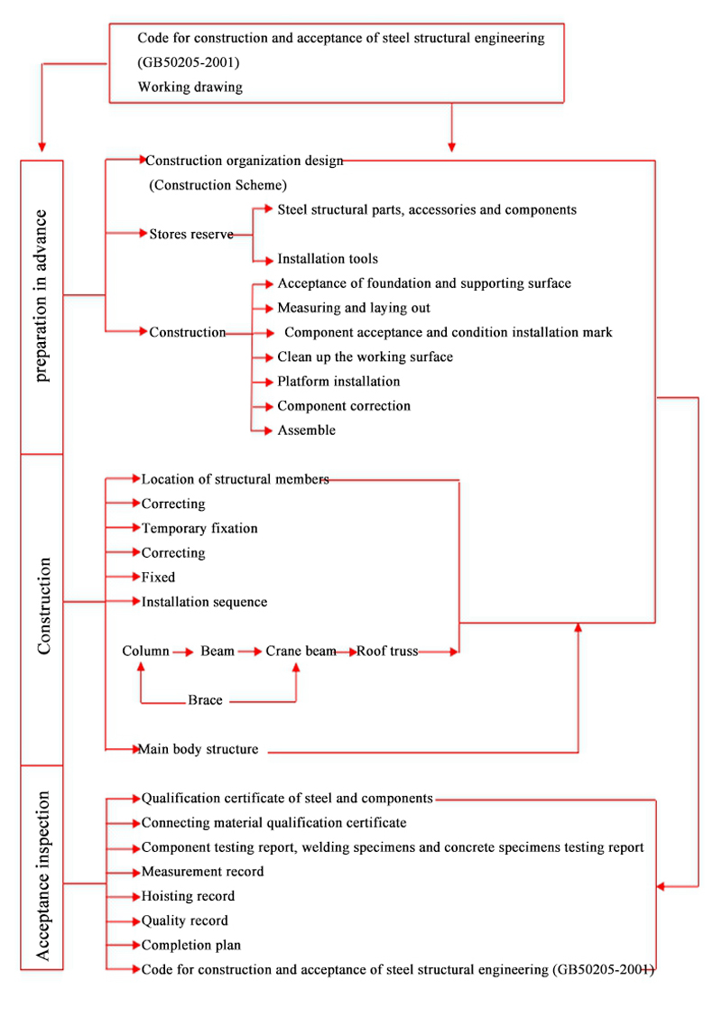
Flow chart of steel structure construction and installation:
Installation process: The constron site should meet the conditions of water, electricity, road and site leveling for short. → Component approach → Crane approach → Steel column hoisting → Hoisting of steel roof truss → Purlin support and tie rod installation → Roofing system installation → Wall system installation → Installation of sporadic components → Ending acceptance data → Hand over a completed project
2. Hoisting of steel structure
2.1 Acceptance of steel components before exit:
Before entering the site, the inspection and supervision departments must check and accept the finished products in accordance with the requirements of construction drawings and the code for construction and acceptance of steel structures (GB50205-2001). The allowable deviation of its steel components must comply with the relevant provisions of GBJ205-83. Products, quality certificates and the following technical documents must be submitted before steel components leaving the factory:
2.1.1 Design change documents, steel structure construction drawings, and the modification part is indicated in the drawings;
2.1.2 Making Protocol Documents for Problem Handling;
2.1.3 Quality certificates and inspection reports for all steel and other materials;
2.1.4 The measured data of friction coefficient of high strength bolts;
2.1.5 List of components to be shipped and transport plan of components.
After components enter the construction site, besides checking the specifications, models and quantities of components, special checks should be made on the vulnerable parts of components which are prone to deformation during transportation. If problems are found, they should be notified and handled. The deformed members should be corrected and re-examined.
To check the factory number of steel components and refer to the construction drawings one by one, the relevant technical personnel must be notified one by one to implement the parts with unclear numbers.
2.2 Pre-assembly of Steel Structure Plant:
Steel structural members such as steel columns and roof trusses, due to transportation conditions and other factors, can not leave the factory entirely. But it must be divided into units. In each unit, the connection form can be assembled by ordinary bolts, high-strength bolts, welding and so on. Due to the different manufacturing errors of each cell in the manufacturing plant, it is difficult to install and connect each cell. In order to ensure the overall installation accuracy of steel structure, it is necessary to pre-assemble in the manufacturing plant, which can reduce the redundant round trip on the site and ensure the progress of the project. After the pre-assembly of the manufacturing plant, the inspection shall be carried out in accordance with the Code for Acceptance and Acceptance of Construction Quality of Steel Structure (GB50205-2001) and relevant construction drawings and technical conditions. After the pre-assembly is completed, it must be checked and accepted jointly with the design, site installation, owner and supervision unit.
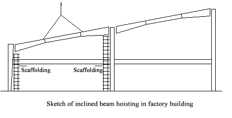
2.3 Lifting of Steel Beams in Roof Frames:
Steel beams are assembled on site using vertical assembly.
2.3.1 Lifting plan: In order to ensure quality, safety, improve production efficiency and reduce labor intensity, according to the site equipment and conditions, the site assembly work should be taken as far as possible. And preventing the lateral instability of the inclined beam.
2.3.2 Selection of lifting points: In order to prevent the distortion and damage of components due to the small lateral stiffness in the lifting process, it is necessary to calculate the lifting points of components in order to coordinate the work and fix the distance between the two lifting points when lifting the hook. For hanging points, in order to prevent local deformation and damage of components, reinforcement ribs or wooden square filling are put in place.
2.3.3 Single assembly hoisting method is adopted in hoisting: The hanging point is tied up by two points, and the bonding point is padded with soft materials to prevent damage of steel components. When lifting, the roof truss should be lifted from the ground about 50 cm to align the center of the roof truss with the installation position, then the roof truss should be lifted slowly to the top of the column, then the roof truss should be rotated by a slip rope to align the roof truss with the top of the column, so that the hook can be put in place slowly. When the roof truss touches the top of the column, the brake should be aligned with the reserved bolt hole, and the bolt should be put into the hole for temporary fixing at the beginning. Verticality correction and final fixing are carried out. Verticality of roof truss is checked by hanging wire hammer. The first roof truss should be connected with wind column and fastened by four slip ropes from both sides. Later, each roof truss can be temporarily fixed and calibrated by four calibrators. After the roof truss is calibrated, various kinds of supports and purlins can be installed, and finally bolts are screwed for final fixing.
2.4 Allowable Error of Steel Beam Installation:
| No. | Project | Standard |
|---|---|---|
| 1 | Height difference of top surface between two ends of beam | L/100 and ≤10mm |
| 2 | Height difference between main girder and girder surface | ±2.0mm |
| 3 | Midspan verticality | H/500 |
| 4 | Flexion (lateral) | L/1000 and 10.0mm |
2.5 Installation of steel support:
2.5.1 Installation of Intercolumn Support: Before installing the inter-column support, the verticality of the steel column must be checked and checked. Then the fixed inter-column support should be installed to make it a rigid bent to reduce the cumulative errors in the installation process of the vertical components. When welding the inter-column support, the verticality of the column should be closely observed and corrected to prevent the permanent error of the column exceeding the acceptance standard.
2.5.2 Installation of roof support system:
Horizontal support installation of upper and lower chords of roof truss adopts integral installation method. If bolt holes dislocation is found, the support system should be dealt with, and the verticality of roof truss should be observed at any time according to the adjustment of support system.
3.Construction of High Strength Bolts
3.1 general situation:
As an important part of steel structure construction, high-strength bolts also occupy a considerable amount of work in this project. According to the requirements of construction design, it is very important to complete the work quickly, high-quality and safely to ensure the realization of the construction objectives of the whole project.
3.2 Technical requirement:
3.2.1 With friction type high strength bolts, the friction coefficient of the connecting surface must meet the design requirements.
3.2.2 The treatment of the contact surface of the connecting parts: before hoisting, oil, dust and floating rust on the friction surface should be removed, and the friction surface should be kept dry and tidy. There should be no flash, burr, welding spatter, welding scar, oxide scale, contamination and so on. If the steel wire brush is applied, it can be removed in time to improve its anti-slip coefficient. Operations are strictly prohibited in rainy days. After rainy days, compressed air is used to blow clean, and then work after drying
3.2.3 High strength bolts should be free to penetrate bolt holes.
3.2.4 The length of high-strength bolts should be strictly controlled during installation to avoid insufficient strength and screw confusion caused by long generation or short generation. The length of high strength bolts shall be added with the length of growth according to the thickness of the connecting parts, as shown in the table below:
| Project | Length | ||
|---|---|---|---|
| Bolt Diameter (mm) | 20 | 22 | 24 |
| Increasing Length of Friction High Strength Bolts (mm) | 30 | 35 | 40 |
3.3 Entry Inspection and Storage of High Strength Bolts:
3.3.1 Storage of high strength bolts should be classified and stored in accordance with the regulations to prevent rain and moisture. Do not use when thread is damaged.When bolts, nuts and washers are corroded, the fastening force should be sampled and checked to meet the requirements of rear use. Bolts should not be contaminated by soil or oil, and they should always be clean and dry.
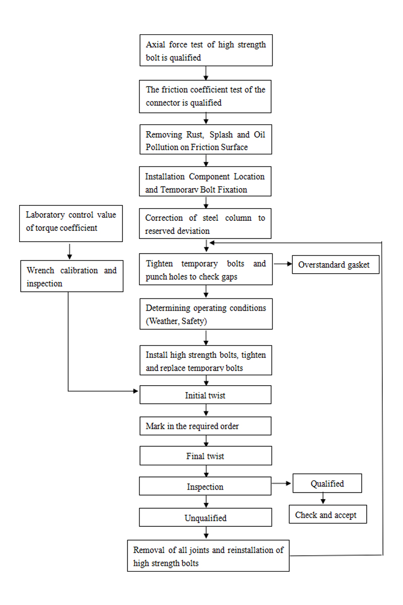
3.3.2 The form, specifications and technical requirements of high strength bolts must conform to the design requirements and relevant regulations. High strength bolts must be tested to determine the torque coefficient or re-check the bolt tension, and only when they meet the requirements can they be used accurately.
Torque coefficient:N=M/D×P
M——Torque on fastening nut(N.m)
D——Nominal diameter of bolt(mm)
P——Fastening Axis Force of Bolts(N)
4.Fastening Procedure and Construction Technology:
4.1 The quality of high-strength bolts must conform to the special regulations of high-strength bolts for steel structures in the Code for Construction and Acceptance of Steel Structures (GB 50205-2001).
4.2 Fastening of high-strength bolts must be done twice. The first is initial screw, which is tightened to 30-50% of the standard pre-tension of bolts. The second is the final screw, which is tightened to the standard pre-tension with a deviation of less than (+10%). In order to make all the bolts in the bolt group bear uniform force, the initial and final screwing should be carried out in the order from the middle to the surrounding.
4.3 The high-strength bolts installed on the same day are screwed at the end of the day. The special electric wrench should be used for the final screwing of the high-strength bolts. The manual wrench can also be used in places where the operation is difficult. The final twisting torque shall be in accordance with the design requirements. When tightened with an electric wrench, the bolt tail and final twisting shall be completed, and the exposed wire shall not be less than 2-3 buckles.
4.4 After the final screw of the high strength big hexagonal head bolt connection pair is completed, the torsion should be checked within 48 hours. The inspection results shall conform to the provisions of Appendix GB50205-2001.
5.Installation process of high strength bolts is as follows: