Installation of Steel Structure Stair
- 11 Jan 2020
- steel structure
1. Installation plan selection
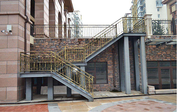
The heaviest component in the steel structure staircase project is the two columns supporting the entire staircase. According to the actual situation on site, the site is reserved during civil construction and tower cranes are used for hoisting in the site.
2. Embedded parts and support position meas urement control
On the vertical and horizontal axes, two theodolites are used to direct the positioning line on the embedded part (including the support) to the telescope's cross wire in parallel, and it is not allowed to move only the center point of the vertical and horizontal positioning line to the telescope's cross wire, or only rotate the embedded parts (including the support). After the embedded parts (including the support) are fixed, when the concrete is poured, it will be offset due to vibration and the lateral extrusion of the concrete pouring. Therefore, two surveyors should be dispatched to monitor deviations with theodolites on two mutually perpendicular axes during pouring and tamping.
If the embedded parts have been buried, they should be handed over to the civil construction company before the steel frame is installed. If any errors occur, contact the owner in time to take measures to rectify them.
3. Steel structure installation
The installation of the steel frame should use the half-floor of the staircase as a unit, that is, use the bracing pipe between the two steel columns of the steel truss as a hoisting unit. After installing the pin, correcting and welding, install the horizontal and longitudinal brace and tie rod system outside the plane. After completion, correct the installation of the stairway of this layer to form a complete force system. The stairway also serves as a platform for the lower half of the steel frame installation.
4. General requirements for components installation
Before installing the component, find out the center of the entire component by calculation, determine the specific location of the lifting point, and tie up the lifting strap (in comparison, the lifting strap is much better than the steel wire rope to protect the surface of the component and prevent slipping during lifting), and then try hoisting. After confirming there is no error, slowly lift the installation position.
4.1 Adjust the elevation to ensure that the design elevation of the assembly point is reached.
4.2 The welding sequence shall be carried out in strict accordance with the welding sequence specified by the welding project.
4.3 efore hoisting, all hoisting components must be carefully inspected. The inspection content should include: checking the weight of the component, the section size, length, bevel condition and lifting point of the component.
4.4 Before hoisting, check and prepare the hoisting equipment and tools. The inspection contents should include: checking the hoisting condition, rigging, hoisting tools, and installation bolts,etc.
4.5 Before hoisting, all the construction workers participating in hoisting shall provide pre-training for technology, drawings and safety.
4.6 When reversing the components, the commander must stand in a place with good sight, and at the same time the commander can communicate with the walkie-talkie at a position that can be seen or known by the hoisting personnel at all levels.
4.7 Check and adjust the installation site before installation. The inspection contents include: elevation, centerline mark, card board, etc.
4.8 After finishing the installation of a component, the builder must make detailed lifting records. Records should include: construction date, weather conditions, component names, component installation locations, counterpart directions, specific dimensions, weights, reports of problems encountered, temporary connections situation, handover procedures, and construction personnel list.
5.Welding Construction
5.1 Electrode drying
Dry the electrode before welding at 300 ~ 350 ℃ and keep it for 90min. The baked electrode is stored in a storage box at a temperature of 100 ~ 150 ° C, and it is used as needed. The electrode shall not be dried more than twice. Welding rod drying records should be made.
5.2 Cleaning
Strictly clean up rust, paint, water, oil, dust and other debris within 10cm of the groove before welding. Check the root gap of the groove before submerged arc welding; check and remove the defects that affect the welding quality inside the groove.
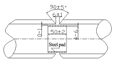
5.3 Specific welding groove joint form
The form of the butt joint of steel material is shown in the figure:
5.4 Welding Sequence
The overall order of steel frame welding is mainly from the middle to the two sides, which releases welding stress and reduces welding deformation.
5.5 Welding Stack Level
Manual arc welding, The welding stacking method of manual arc welding adopts multi-layer multi-channel stacking method, narrow-channel welding. The thickness of each track should not exceed 3mm.
5.6 Welding bead inspection
5.6.1 The appearance of the weld bead should be smooth and beautiful, and the appearance must be free from surface defects such as cracks, pores, overshooting, slag inclusions, welding bulges, arc craters, underwelding, and fusion spatter. The appearance of the weld bead shall be smooth and flat, and the ripples shall be fine, as well as the width shall be uniform.
5.6.2 Butt joints weld bead quality should reach Class II, and 20% non-destructive testing is performed 24 hours after welding. The testing method is based on actual situation, mainly is ultrasonic testing. Non-destructive testing is performed by qualified personnel. For internal defects detected, mark the position and length of the defect with a marker and make a record. Welding technicians prepare the repair process based on the inspection report and structural characteristics, and then communicate it to the welder in a technically complete form. Internal defects found through non-destructive testing should be removed by carbon arc gouging (see the table below for carbon arc gouging parameters) Then repair welding by the same welding process as the formal welding. Before welding, use a manual grinding wheel to remove the carburized layer of the base metal after planing to prevent the base metal from increasing carbon during welding. The reverse repair welding should adopt the same welding process as the formal welding. The number of reverse repairs in the same place must not exceed three times.
Process parameters of carbon arc gouging
| Carbon rod diameter(mm) | Arc length(mm) | Air pressure(Mpa) | Polarity | Current(A) | Gouging speed(m/min) |
|---|---|---|---|---|---|
| 5 | 1~2 | 0.39~0.59 | DC reverse connection | 250 | 0.5~1.0 |
| 6 | 1~2 | 0.39~0.59 | DC reverse connection | 280~300 | 0.5~1.0 |
| 7 | 1~2 | 0.39~0.59 | DC reverse connection | 300~350 | 1.0~1.2 |
5.6.3 Welding construction information
Welding construction information includes material certification, qualification certificate, welding rod drying records of welding consumables, retroactive welding construction records, repair records, flaw detection reports, and quality assessment of steel structures welding sub-item projects.