Light Portal Frame Steel Structure Design
- 04 Jun 2020
- steel structure
The portal frame is a form of steel structure that effectively uses materials. Due to the small size of the components, the height of the house is reduced accordingly, reducing the volume and weight of building. The components can be mass-produced in the factory, and high-strength bolts are used for installation on the site, which is simple and fast, and the construction period is short. At the same time, the portal frame is simple and beautiful in appearance, which can be applied to single-span and multi-span factories, warehouses and various public buildings covering large areas in housing construction.
1. Building Features
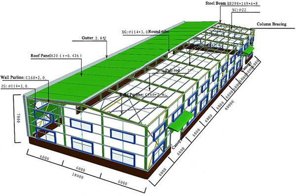
1.1 Lightweight,both the roof and walls are profiled steel plates to reduce the self-weight of the building;
1.2 Crane ton: A1 ~ A5 working grade bridge crane 20t; Suspended crane 3t.
1.3 Common span: 18-30m, height 4.5-9m. The regulations stipulate that the span can be up to 36m.
2. Structure features
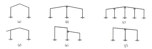
2.1 The main steel structure adopts portal rigid frame, which can be single-span, double-span or multi-span, and can also with attached span. Making the center column into a swing column reflects the principle of concentrated use of materials.
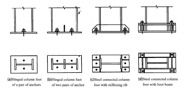
2.2 Adopting the method of changing the section of components to adapt to the change of bending moment is one of the technical measures to lighten the portal frame . The column foot is commonly hinged, (When there is a bridge crane, it is fixed with equal section and column foot)
2.3 The spacing of the rigid frame is generally about 6m, and 7.5 ~ 9m can also be used. If the spacing is too large, the amount of steel used for purlins will be increased.
Length of temperature section: 300m in vertical direction; 150m in horizontal direction. When the above values are not exceeded, in general, the influence of temperature stress and temperature deformation can be ignored.
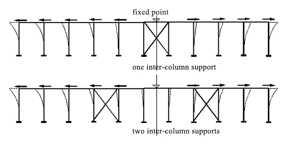
The longitudinal horizontal stiffness of the inter-column support is much greater than that of the single column (about 10 to 20 times), so the fixed point of the longitudinal temperature deformation of the workshop is close to the midpoint of the inter-column support (when there are two inter-column supports,it is the midpoint of the two support distance).
The new regulation added: "When there is a calculation basis, the length of the temperature section can be appropriately increased". It is considered that there are many limit factors affecting the length of the temperature section, which cannot be reflected one by one in the regulation, allowing the designer to consider increase or decrease according to the specific situation.
When the length of the temperature section exceeds the value specified in the specification, the calculation of the temperature stress shall be carried on or the temperature expansion joint shall be set.
Two methods of temperature expansion joint:
a. Adopt oblong holes at the bolt connection of the overlapping purlins;
b. Set up double columns
In addition, the connection between the crane beam and the column should use oblong holes.
2.4 The slope of the rigid frame inclined beam depends on the roof drainage slope, generally i = 1/8 ~ 1/20.
Reduce the thickness of the web plate of the components, generally the web plate thickness is 4 ~ 10mm, (4mm is the lower limit specified in the regulations), mainly use the post-buckling strength of the web plate section.
2.5 The purlin is made of cold-formed thin-walled steel, and the cross-section is generally C-shaped or Z-shaped steel (when the slope is large, the main axis can be parallel to the ground). Purlin thickness is generally 1.5 ~ 3.0mm, 1.5mm is the lower limit specified in the regulation.
2.6 Support System:
A roof support system and an inter-column support system must be provided. The roof support is arranged at the two ends of the temperature section or the second compartment at the end (in this case, the rigid tie bars should be set in the first compartment).
The inter-column support is set between the same columns as the roof support. When there is no crane, the spacing is generally 30 ~ 45m, not more than 60m. When there is a crane, the inter-column support should be set in the middle part of the temperature section.
The support is generally a cross, and the section is made of tensioned round steel or small angle steel.
3. Characteristics of load calculation
3.1 For evenly distributed live load of roofs that are not suitable for people, the earlier load specification is 0.3 kN / m2. Later, it was found that the counterweight roof was lower, so it was changed to 0.5 kN / m2 in the 74 specification. After adopting the probabilistic limit state design method, it is found that the reliability of the structure dominated by dead load (concrete structure) is reduced, so it was increased to 0.7kN / m2.
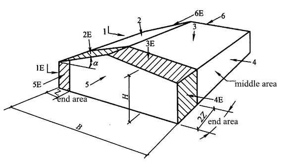
3.2 "Technical Regulations for portal ridge frame light Steel Structures Houses" have special regulations on the shape factor under wind load. There are special regulations for rigid frames, purlins, roof panels, wall beams, etc. In particular, it should be noted that the wind load carrier coefficient of the end area of the house is different from the middle area.
4. Design features of purlins
4.1 Purlins are thin-walled components. In the stressed state, the component plates may lose local stability and buckle, but they can still bear after buckling (using the thin film effect, that is, the tension field). The strength after buckling is used in the design, and the strength calculation is generally carried out by the method of effective section.
4.2 The overall stability calculation of purlin is divided into two cases:
a. Under the action of wind pressure, the purlin braces set in the general profiled steel plate (provided that there are sufficient anti-shear pieces) and the compression area can play a lateral restraint role.
b. Under the action of wind suction, the lower flange is compressed (the purlins set continuously have similar conditions under the action of wind pressure), and the stress state is similar to the elastic foundation beam.Some studies believe that it can be calculated according to the compression bar of the elastic foundation beam. The restraining effect of the tension flange on it can be regarded as the effect of the elastic foundation beam. The section torsional and lateral bending effects are equivalently converted into lateral loads acting on the lower flange to simplify calculations.
Structural requirements may also be adopted, such as setting up a angle brace.
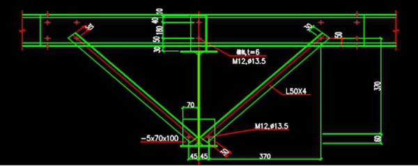
Construction way of purlins - adding angle brace
5. Features of component design
5.1 The axial force of the inclined beam is large, and it is generally designed according to pressing and bending components, to meet the requirements of strength, overall stability, and local stability. The web plate of I-shaped cross-section can also be designed according to the strength after buckling, but the maximum height to thickness ratio should not be greater than 250.
Design features of I-shaped cross-section components web considering strength after buckling:
(a)The provisions do not apply to crane beams. Due to insufficient information, repeated buckling may cause fatigue cracks at the edges of the web plate.
(b)The strength calculation of the web after shear buckling adopts the concept of tension field to make the ultimate shear force greater than the buckling shear force. To accurately determine the shear value of the tension field, the width of the tension field needs to be calculated, which is relatively complicated. An approximate formula equivalent to the lower limit is used to simplify the calculation.
(c)Adopting the strength after buckling of the web plate, even if the hw / tw is very large, as long as the anti-shear bearing capacity of the web plate is not lower than the actual maximum shear force of the components, it is generally no longer considered to set stiffening ribs.
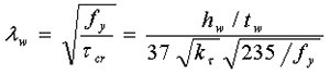
(d)After the strength after buckling of web plate is used, the flexural and compressive bearing capacity of the components is reduced. At this time, the cross-sectional characteristics should be calculated according to the effective width.The effective width of the pressure zone is taken:
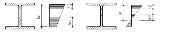
When all sections are compressed:he=hw when part of the sections are compressed:he=hc
(e) The anti-shear bearing capacity Vd after buckling of web plate shall be the sum of buckling shear force and tensile field shear force, calculated by the following formula:
When λw 0.8 Vd=hwtwfv (a)
When 0.8<λw<1.4: Vd=hwtwfv[1-0.64(λw-0.8)] (b)
When λw1.4: Vd=hwtwfv(1-0.275λw ) (c)
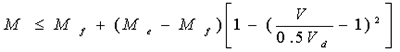
In the formula λw——is used for the anti-shear calculation of general height to thickness ratio of web plate
(f)The strength of I-shaped section bending components under the action of shear force and bending moment, adopts the basic calculation formula of European standard EC3:
When V 0.5 Vd, MMe (a)
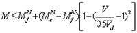
When 0.5Vd< V Vd\, (b)
Mf —The bending moments borne by the two flanges of the beam,to biaxially symmetrical beams
Mf=Af( hw·+t)f(Af is a flange cross- section area);
Me—Bending moment borne by the effective section of the component,Me=We f
(g)The strength of the I-shaped section bending component under the combined action of shear force, bending moment and axial force is calculated as follows basic formula:
When V0.5 Vd, MMe -N We/ Ae (a)
when0.5VdV < Vd,
MNf—The bending moment borne by the two flanges of the beam when under pressure, to biaxially symmetrical beams,
MNf=Af ( hw·+t)(f - N/A );
Ae —Effective cross-sectional area of component.
(h)Considering the Stiffening rib design of strength after buckling of web plate
When the strength after buckling of the beam web plate is used, in addition to bear the concentrated load and the flange turning, the middle stiffening rib also bears the pressure generated by the tension field. The pressure is calculated as follows:Ns=V - 0.9hwtwcr
In the formula, Ns is the pressure generated by the tension field after web plate buckling; cr is the critical shear stress. The above formula is larger than the theoretical value to consider the adverse effect of the horizontal component of the tension field tension.
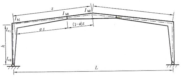
5.2 When the variable cross-section portal rigid frame is adopted, the rigid frame column is wedge-shaped, and its calculated length coefficient in the plane of the rigid frame can no longer be applied to "Steel Structure Design Code". The regulations have other special specifications.
The calculation formula of the overall stability of the variable cross-section column in the rigid frame plane still adopts the form of the steel structure design code.
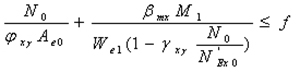
The axial force takes the small end, and the bending moment takes the big end. The equivalent bending moment coefficient take 1.0 according to the rigid frame with lateral displacement
5.3When the swing column is unstable, its deflection curve is similar to the Euler column hinged at both ends, so the calculated length is taken as 1.0.
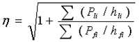
5.4 The swinging column connected to the rigid frame produces horizontal force on the rigid frame during buckling, which reduces the critical force of the rigid frame column. Therefore, the calculated length of the rigid frame column should be multiplied by the increase factor:
6. Deformation control
Properly relaxing the deflection of the frame beam and the displacement limit of the frame column top is a guarantee for the lightweight of portal frame. Such as:
Displacement limit of the frame column top
No crane, light wall panel h/60(h/150)
No crane, masonry wall h/100(h/150)
With crane, and the crane has a cab h/400
With crane, ground operation h/180(h/400)
Frame inclined beam deflection L/180( L/400)
7. Steel structure joint design
7.1 The portal rigid frame structure generally divides the transportation and installation units in the span of the beam-column node and the frame beam。
The connection of the inclined beam and the column of the portal rigid frame can adopt three forms of end plate vertical placement, end plate horizontal placement and end plate oblique placement.
7.2 In order to ensure the rigidity of the nodes, the nodes should be connected by friction type or pressure type high strength bolts, which are generally arranged in pairs.
7.3 In order to reduce the influence of the lever force, the thickness of the end plate connected with high-strength bolts should not be too thin, generally 1.5 ~ 2d, or set stiffening rib.
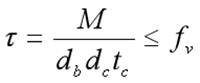
7.4 The connection is designed according to the maximum internal force. The nodal domain where the inclined beam and column intersect should be checked for shear strength
The shear stress on the node web plate area with the boundary of the column flange and lateral stiffeners should meet the following requirements:
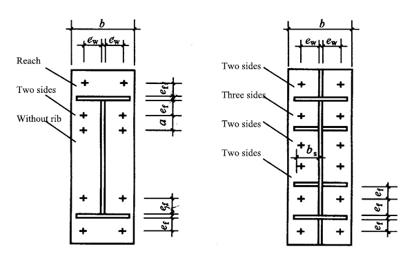
7.5 Column foot composition of portal rigid frame