Stability of steel structure
- 24 Dec 2019
- steel structure
1. introduction
With the rapid development of iron and steel industry, and due to many advantages of steel structure , this kind of steel structure, which is considered as a green environmental protection product, is the development direction of architecture. However, because the compressive strength of reinforced concrete is more than 20 times higher, compared with concrete members, the designed steel members bearing the same stress function have the characteristics of small section size and long and thin members. When the steel members with compression area such as compression and bending are not treated properly, instability is likely to occur. Therefore, in order to improve the section efficiency and give full play to the strength of steel, steel structure is generally made into thin-walled structure, which makes steel structure have great competitiveness in the long-span scheme, but at the same time, it also brings disadvantages: small structural rigidity, prominent stability problems, stability problems generally lie in the design of steel structure, so only by dealing with the stability problems of steel structure can we make economy reasonable design.
2. Concept of instability and types of stability problems
2.1 Concept of instability
The structure or component in the balance position will deviate from its balance position under any small external disturbance. When the external disturbance is removed and can still automatically return to the initial balance position, the initial balance state is stable; if the external disturbance is removed and cannot return to the initial balance position, the initial balance state is unstable. So the equilibrium state is an intermediate state in the transition from stable state to unstable state. Stability analysis is to study whether the equilibrium state of structure or component is stable. Because of the instability of the equilibrium form, the structure or component changes from the initial equilibrium position to another equilibrium position, which is called buckling or instability.
2.2 Types of stability problems
The instability phenomenon of steel structure is various, but in terms of its properties, it can be divided into the following three categories:
2.2.1 Equilibrium bifurcation instability (branch point instability)
As shown in Figure 1, it is an ideal straight bar under central compression. When p < PCR, the straight line is stable; when p > PCR, the straight line balance is unstable. When the load p acting on the end of the member does not reach a certain limit value, the member always maintains a straight and stable equilibrium state,△ = 0, the member only bears uniform compressive stress, and only produces corresponding compression deformation along the axis of the member.
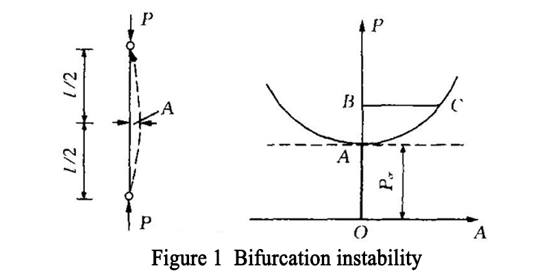
If a small interference is applied in its transverse direction, the component will show a small deformation, but once the interference is removed, the component will immediately return to the original straight-line equilibrium state. If the load used for the upper end reaches the limit value of PCR, the member will bend, which is ≠ 0. At this time, the linear equilibrium state is not stable, and the member will change from the original straight equilibrium state to the adjacent equilibrium state with small bending. OB represents linear balance, AC represents bending balance. It means that the OA, AB and AC line segments with different equilibrium forms are taken as the equilibrium path with the increase of load P. The equilibrium path branches at point a, which is called branch point, and the load value of the store is called branch point load, which is PCR. The central compression bar on the balance path OA is in a stable linear equilibrium state; ab is an unstable linear equilibrium state; AC is a stable bending equilibrium state. The bifurcation point is the boundary point for the transition of the linear equilibrium state from stable to unstable. When the straight-line equilibrium loses stability, there will be the possibility of two kinds of equilibrium states of different mechanical properties, i.e. axial compression and compression bending. The instability phenomenon with the above characteristics is called branch point instability.
2.2.2 Instability of extreme point (or stability of unbalanced bifurcation)
For eccentrically compressed members, when the load starts to act, keep the balance of bending form until the critical state ends. As shown in Figure 2, the balance path is divided into OA and ab ends. The equilibrium state on the OA segment is stable. The equilibrium state of AB on the descending segment is unstable. In the stage of equilibrium and stability, the equilibrium form is only the aggravation of deformation under the original equilibrium form, there is no bifurcation point in different deformation states, only the extreme point. Therefore, the instability is not a branch stability problem, so it is called extreme point instability.
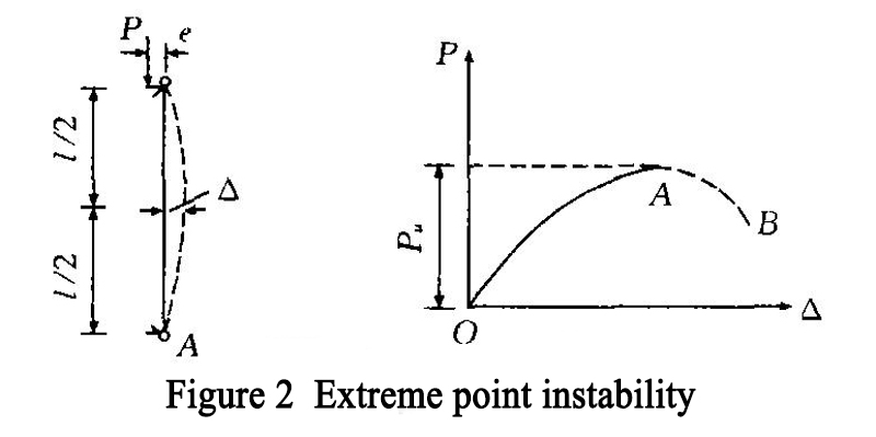
In fact, when the load is added to point a, the member will be damaged immediately due to the instability of the equilibrium when it is slightly disturbed, so it is difficult to draw the AB line of the descent section.
Point a is called extreme point, and the corresponding load is called stable ultimate load or collapse load, PU.
Because there is no change in the form of equilibrium, it can be seen that the instability of branch points is abrupt, while the instability of extreme points is not abrupt.
In the actual axial compression members, because of the initial bending and load action point slightly deviate from the initial eccentricity of the member axis, most of the stability problems in the project belong to the extreme point instability. For example, the elastic-plastic bending and torsional instability of biaxial bending members and biaxial bending members belong to the extreme point instability. In practical engineering, the problem of extreme point instability is transformed into branch point instability. Some parameters [4] are introduced to reflect the difference between them.
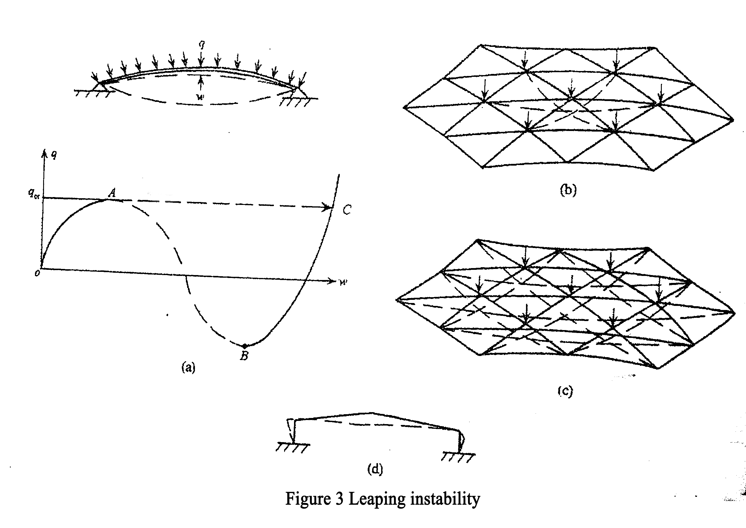
2.2.3 Jump instability
As shown in Figure 3 (a), the arch structure with flat hinge at both ends has deflection ω under the action of uniformly distributed load Q, and its load deflection curve also has a stable rising section A. However, because the structure has been damaged, when it reaches the highest point a of the curve, it will suddenly jump to a non adjacent point C with great deformation, and the arch structure will immediately sag.On the load deflection curve, the dotted line AB is unstable. Although the BC section is stable and rising all the time, it cannot be used because the structure has been damaged. The load corresponding to point a is the critical load of the flat arch. This instability phenomenon is called jump instability. It has neither equilibrium bifurcation point nor extremum point, but it has some similar phenomena with instability bifurcation instability. It jumps to another stable equilibrium state after losing stable equilibrium. The jump instability may also occur in the shallow shell and the flat reticulated shell. In Figure 3 (b) is the point jump instability of latticed shell structure with local depression, while Figure 3 (c) is the overall jump instability. For a large-span portal steel frame with gentle slope, when the rigidity of the steel frame beam is very weak and the rigidity of the lateral movement is very strong, the jump instability as shown in Figure 3 (d) may occur. The initial inclination of the beam, that is, the slope of the beam, has a great influence on the deformation of this kind of structure, which is similar to the bifurcation instability with defects. Defects also have a great influence on such structures.
It is very important to distinguish the types of structural instability, otherwise it is impossible to estimate the stability bearing capacity of the structure correctly. For the structure with equilibrium bifurcation instability, as mentioned above, the theoretical buckling load area is divided into three cases, one is closer to the actual limit load, one is greater than the actual limit load, and one is far less than the actual limit load. Only the large deflection theory can reveal the post buckling performance of the structure with equilibrium bifurcations, but the calculation process of the large deflection theory is very complicated. For the stable critical state, the adjacent buckling configuration of the structural system can be maintained at the load exceeding the bifurcation buckling load; but for the unstable critical state, the adjacent buckling configuration of the structural system can only be maintained at the load lower than the bifurcation buckling load.
3. Factors affecting the stability of steel structure
In the design, steel structure is generally regarded as a perfect structural system. In fact, there are some random factors that affect the stability of steel structure. Generally, the random factors that affect the stability of steel structure are divided into three categories:
3.1 Physical and geometric uncertainties: such as material (elastic modulus, yield stress, Poisson's ratio, etc.), member size, sectional area, residual stress, initial deformation, etc.
3.2 Statistical uncertainty: in the statistics of physical and geometric quantities related to stability, the probability density distribution function is always selected according to the limited samples, so it brings some experience. This kind of uncertainty is called statistical uncertainty because of the lack of information.
3.3 Model uncertainty: in order to analyze the structure, the proposed assumptions, mathematical models, boundary conditions and various factors that are difficult to be reflected in the calculation of the current technical level, resulting in the difference between the theoretical value and the actual bearing capacity, are all attributed to the model uncertainty.
4. Calculation method of steel structure stability
The analysis methods of the stability of steel structure are all aimed at the deformation of the structure under the external load, which should correspond to the deformation of the studied structure or component when it loses stability. Because of the nonlinear relationship between the structural deformation and the load, the stability calculation belongs to the geometric nonlinear problem, which adopts the second-order analysis method [5]. The stability calculation, whether buckling load or ultimate load, indicates the stability bearing capacity of the calculated component or structure. There are three calculation methods for stability problems:
4.1 Balance method (static method)
Neutral balance method or static balance method, which is called balance method for short, is the most basic method to solve the limit load of structural stability. The equilibrium method is to establish the equilibrium differential equation and then solve the critical load according to the stress condition of the structure after the micro deformation. In establishing the bending equilibrium equation of the ideal axial compression member, the following assumptions are made:
4.1.1 When the member is a straight bar with constant cross-section;
4.1.2 The pressure always acts along the original axis of the component;
4.1.3 The material conforms to Hooke's law, that is, the relationship between stress and strain becomes linear;
4.1.4 The member conforms to the plane section assumption, that is, the plane section before the member deformation is still plane after the deformation;
4.1.5 The bending deformation of the component is small, and the curvature can be approximately expressed by the second derivative of the deflection function, so that the differential equilibrium equation can be established: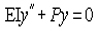 , by substituting the corresponding boundary conditions, the critical load of the axial compression component supported by the hinge at both ends can be obtained
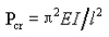 .
.
4.2 Energy method
Energy method is an approximate method to solve the stable bearing capacity. The main ways to solve the critical load with energy method are energy conservation principle and potential energy standing value principle
4.2.1 The principle of conservation of energy to solve critical load
When the conservative system is in equilibrium, the strain energy stored in the structural system is equal to the work done by the external force, which is the principle of energy conservation. Timoshenko method is used to solve the problem of elastic stability of structures based on the principle of conservation of energy:
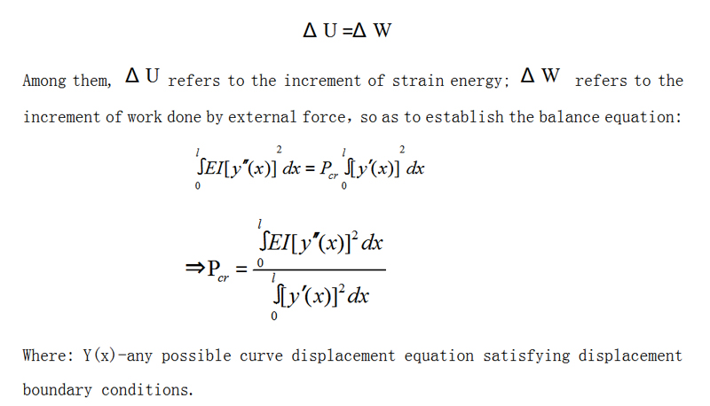 .
.
4.2.2 The principle of potential energy standing value to solve critical load
The principle of potential energy standing value refers to: when the displacement of a structure is slightly changed but the total potential energy is unchanged, that is, when the total potential energy has a standing value, the structure is in equilibrium. expression:
dΠ=dU-dW=0
Where: Du refers to the change of internal variable energy caused by virtual displacement, which is always positive; DW refers to the work of external force on virtual displacement.
The principle of potential energy standing value is equivalent to the equilibrium equation, which can be used to solve the problem of elastic stability of complex structures. If it is difficult to establish the equilibrium equation directly for many structures, we can first write out the total potential energy π of the structure, and then use d π = 0 to get the equilibrium equation. In addition, the shape of the deflection curve of the member can be assumed first, and the deflection curve equation can be given, which can be substituted into the total potential energy Π, and the critical load can be solved by D Π = 0。
4.2.3 Dynamic method
If the structural system is in equilibrium state, if a small disturbance is applied to make it vibrate, then the deformation and vibration acceleration of the structure are related to the load already acting on the structure. When the load is less than the stable limit value, the direction of acceleration and deformation is opposite, so after the interference is removed, the movement tends to be static, and the structure's balance state is stable; when the load is greater than the limit value, the direction of acceleration and deformation is the same, even if the interference is removed, the movement is still divergent, so the structure's balance state is unstable; the load in the critical state is the junction The buckling load of the structure can be obtained by the condition that the vibration frequency of the structure is zero. The dynamic method belongs to the problem of structural dynamic stability.
In the calculation of balance method and energy method, it can be solved by analytic method or numerical method. The numerical method using computer technology has become a basic method to study structural stability in modern times.
5. The principle of stable design of steel structure
According to the characteristics of the stability problem, in order to better ensure that the members in the steel structure stability design will not lose stability, the following principles must be paid attention to:
5.1 The overall layout of the structure must consider the stability requirements of the whole system and its components. At present, most of the structures are designed according to the plane system, such as truss and frame. To ensure that these plane structures do not cause plane instability, it needs to be solved from the overall layout of the structure, that is, to design the necessary supporting members. That is to say, the plane stability calculation of plane structural members must be consistent with the structure layout.
5.2 The commonly used method of member stability calculation is based on some simplified assumptions or typical cases, and the designed structure must conform to these assumptions. At present, in the design of single-layer and multi-layer frame structure, the stability analysis of frame is often replaced by the stability calculation of frame column instead of frame stability analysis. When this method is adopted, only through the overall stability analysis of the frame, can the calculation of column stability be equivalent to the calculation of frame stability. However, there are many kinds of practical frameworks. In order to simplify the calculation, some typical conditions need to be set. Five basic assumptions are adopted in the calculation of length coefficient given by frame columns, the third of which is "all columns in the frame lose stability at the same time, that is, each column reaches its critical load at the same time". According to this false, the commonly used method of stability calculation for members of each column of the frame is usually based on certain simplified assumptions or typical situations. Only when the designer is sure that the designed structure conforms to these assumptions can it be correctly applied. For the columns without or with weak support and sway columns, the code considers the increasing coefficient, so that the actual calculation method is consistent with the premise assumption and the specific calculation object.
5.3 The detailed structure of the design structure and the stability calculation of the components must cooperate with each other to make them consistent. For example, the overall stability of the beam has an important relationship with the end connection structure.
6. Problems in the study of stability of steel structure system
Although the research on the stability of steel structure system has made some progress, there are some problems that can not be ignored
6.1 At present, beam column element theory has become the main research tool in the study of the stability of latticed shell structure. However, it is difficult to say whether the beam column element can truly reflect the stress state of the latticed shell structure. Although some scholars have revised the beam column element, the main problem is how to reflect the coupling effect of axial force and bending moment.
6.2 In the design of long-span structure, the relationship between the overall stability and the local stability is also a problem worthy of discussion. At present, a unified stability safety factor is taken in the design of long-span structure to reflect the correlation between the overall stability and the local stability.
6.3 At present, there is not a complete and reasonable theoretical system to analyze the stability of pretensioned structure system.
6.4 There are many random factors in the study of the stability of steel structure system. At present, most of the problems dealt with in the structural random impact analysis are limited to the determined structural parameters and random load input. In the actual project, because of the uncertainty of structural parameters, there will be significant differences in the structural response. So we should focus on the problems of extreme instability, interference buckling and jump instability.
7. Conclusion
The stability problem is very complex, especially when there are initial defects, residual stress and the influence of nonlinear factors, it increases the difficulty of solving the stability problem. In addition, there are many unsolved problems in the research field of engineering structure stability. For example, the double nonlinear dynamic stability problems of long-span bridges, long-span thin shells, long-span space latticed shells, high-rise and super high-rise structures. Only by deeply understanding these problems can the theoretical design of steel structure stability be improved continuously.