Steel structure calculation table
- 16 Nov 2019
- steel structure
In order to ensure the bearing capacity of the steel structure and prevent brittle failure under certain conditions, it should be considered according to the importance of the steel structure, load characteristics, structural form, stress state, connection method, steel thickness, working environment and so on. We should choose suitable steel grade and material properties.
The steel of load-bearing structure should adopt Q235 steel, Q345 steel, Q390 steel and Q420 steel, and the quality should conform to the current national standard "carbon structural steel" GB/T 700 and "low alloy high-strength structural steel" GB/T 1591. Provisions. When other grades of steel are used, they should also comply with the relevant standards and requirements. For Q235 steel, it is advisable to use killed steel or semi-killed steel.
The steel of the load-bearing structure shall have the qualification guarantee of tensile strength, elongation, yield strength and sulfur and phosphorus content, and the welding structure shall have the qualification guarantee of carbon content.
Steels bearing the load-bearing structure and important non-welded load-bearing structures shall also have a qualification guarantee for the cold bend test.
For steels that need to be tested for fatigued welded structures, they should have a qualification guarantee for normal temperature impact toughness. When the structural working temperature is equal to or lower than 0 °C but higher than -20 °C, Q235 steel and Q345 steel should have the qualification guarantee of 0 °CC impact toughness; Q390 steel and Q420 steel should have the qualification guarantee of -20 °C impact toughness. . When the working temperature of the structure is equal to or lower than -20 °C, Q235 steel and Q345 steel should have the qualification guarantee of -20 °C impact toughness; Q390 steel and Q420 steel should have the qualification guarantee of -40 °C impact toughness.
For non-welded structural steels that need to be checked for fatigue, they should also have the guarantee of normal temperature impact toughness. When the structural working temperature is equal to or lower than -20 °C, Q235 steel and Q345 steel should have the guarantee of 0°C impact toughness; Q390 steel and Q420 steel should have a qualification guarantee of -20 °C impact toughness.
When the Z-direction steel is used to prevent the laminar tearing of the steel, the material of the welding load-bearing structure shall comply with the current national standard "Thickness-oriented performance steel plate" GB/T 5313.
The design value of the strength of the steel (the standard value of the material strength divided by the resistance partial factor) shall be adopted according to Table 1-1 according to the thickness or diameter of the steel. The strength design value of steel castings shall be as shown in Table 1-2. The strength design values of the connections shall be in accordance with Tables 1-3 through 1-5.
Strength design value of steel (N/mm2) Table 1-1
| Steel material | Tensile, compression and bending resistance f | Shear fv | End pressure (planing top) fce | Number | Thickness or diameter(mm) |
|---|---|---|---|---|
| Q235steel | ≤16 | 215 | 125 | 325 |
| >16~40 | 205 | 120 | ||
| >40~60 | 200 | 115 | ||
| >60~100 | 190 | 110 | ||
| Q345steel | ≤16 | 310 | 180 | 400 |
| >16~35 | 295 | 170 | ||
| >35~50 | 265 | 155 | ||
| >50~100 | 250 | 145 | ||
| Q390 steel | ≤16 | 350 | 205 | 415 |
| >16~35 | 335 | 190 | ||
| >35~50 | 315 | 180 | ||
| >50~100 | 295 | 170 | ||
| Q420 steel | ≤16 | 380 | 220 | 440 |
| >16~35 | 360 | 210 | ||
| >35~50 | 340 | 195 | ||
| >50~100 | 325 | 185 | ||
Note: The thickness in the table refers to the thickness of the steel in the calculation point, and the thickness of the thicker plate in the section of the axial force bearing member.
Strength design value of steel castings (N/mm2) Table 1-2
| Steel number | Tensile, compression and bending resistance f | Shear fv | End pressure (planing top) fce |
|---|---|---|---|
| ZG200-400 | 155 | 90 | 260 |
| ZG230-450 | 180 | 105 | 290 |
| ZG270-500 | 210 | 120 | 325 |
| ZG310-570 | 240 | 140 | 370 |
Weld strength design value (N/mm2) Table 1-3
| Welding method and welding rod model | Steel component | butt weld | fillet weld | ||||
|---|---|---|---|---|---|---|---|
| number | Thickness or diameter(mm) | Compressive pressur efcw | When the weld quality is the following grade, tensile strength ftw | shear | Tensile, compressive and shear resistant | ||
| 1 grade/2 grade | 3 grade | fvw | ffw | ||||
| Manual welding of semi-automatic, semi-automatic and E43 electrodes | Q235 steel | ≤16 | 215 | 215 | 185 | 125 | 160 |
| >16~40 | 205 | 205 | 175 | 120 | |||
| >40~60 | 200 | 200 | 170 | 115 | |||
| >60~100 | 190 | 190 | 160 | 110 | |||
| Manual welding of semi-automatic, semi-automatic and E50 electrodes | Q345 steel | ≤16 | 310 | 310 | 265 | 180 | 200 |
| >16~35 | 295 | 295 | 250 | 170 | |||
| >35~50 | 265 | 265 | 225 | 155 | |||
| >50~100 250 | 250 | 250 | 210 | 145 | |||
| Manual welding of semi-automatic welding, semi-automatic welding and E55 welding rod | Q390 steel | ≤16 | 350 | 350 | 300 | 205 | 220 |
| >16~35 | 335 | 335 | 285 | 190 | |||
| >35~50 | 315 | 315 | 270 | 180 | |||
| >50~100 | 295 | 295 | 250 | 180 | |||
| Manual welding of semi-automatic welding, semi-automatic welding and E55 welding rod | Q420 steel | ≤16 | 380 | 380 | 320 | 220 | 220 |
| >16~35 | 360 | 360 | 305 | 210 | |||
| >35~50 | 340 | 340 | 290 | 195 | |||
| >50~100 | 325 | 325 | 275 | 185 | |||
Note: 1. The welding wire and flux used in automatic welding and semi-automatic welding shall ensure that the mechanical properties of the deposited metal are not lower than the current national standard "Solid for submerged arc welding of carbon steel" GB/T 5293 and "Submerged arc welding for low alloy steel". Flux" GB/T 12470 related provisions;
2. The weld quality grade shall comply with the current national standard "Code for the Acceptance of Construction Quality of Steel Structure Engineering" GB 50205. For butt welds with a thickness of less than 8 mm steel, it is not advisable to use ultrasonic flaw detection to determine the weld quality grade;
3. The design value of the strength of the butt welds in the flexural compression zone is fcw, and the design value of the flexural tension zone is taken as ftw.
Bolt connection strength design value (N/mm2) Table 1-4
| Pressure-type connection high-strength bolt | plain bolt | anchor bolt | Pressure-type connection High strength bolt |
||||||||
|---|---|---|---|---|---|---|---|---|---|---|---|
| C grade bolt | A grade/B grade bolt | ||||||||||
| tensile | shear | pressure-bearing | tensile | shear | pressure-bearing | tensile | tensile | shear | pressure-bearing | ||
| ftb | fvb | fcb | ftb | fvb | fcb | fta | ftb | fvb | fcb | ||
| Plain bolt | 4.6 grade/4.8grade | 170 | 140 | - | - | - | - | - | - | - | - |
| 5.6grade | - | - | - | 210 | 190 | - | - | - | - | - | |
| 8.8 grade | - | - | - | 400 | 320 | - | - | - | - | - | |
| anchor bolt | Q235 steel | - | - | - | - | - | - | 140 | - | - | - |
| Q345 steel | - | - | - | - | - | - | 180 | - | - | - | |
| Pressure-type connection high-strength bolt | 8.8 grade | - | - | - | - | - | - | - | 400 | 250 | - |
| 10.9 grade | - | - | - | - | - | - | - | 500 | 310 | - | |
| component | QZ35steel | - | - | 305 | - | - | 405 | - | - | - | 470 |
| Q345 steel | - | - | 385 | - | - | 510 | - | - | - | 590 | |
| Q390 steel | - | - | 400 | - | - | 530 | - | - | - | 615 | |
| Q420 steel | - | - | 425 | - | - | 560 | - | - | - | 655 | |
Note: 1. Class A bolts are used for bolts with d ≤ 24 mm and l ≤ 10 d or l ≤ 150 mm (small value); Class B bolts are used for bolts with d > 24 mm or l > 10 d or l > 150 mm (small value). d is the nominal diameter and l is the nominal length of the screw;
2. The accuracy of the A and B bolt holes and the surface roughness of the hole wall, the allowable deviation of the C-class bolt holes and the surface roughness of the hole wall shall comply with the requirements of the current national standard "Code for the Acceptance of Construction Quality of Steel Structures" GB 50205.
Strength design values for rivet connections (N/mm2) Table 1-5
| Rivet steel number and components Steel grade |
Tensile (nail head pull) | shear fvT | pressure-bearing fcT | |||
|---|---|---|---|---|---|---|
| ftT | I hole | II hole | I hole | II hole | ||
| Rivet | BL2 or BL3 | 120 | 185 | 155 | - | - |
| Component | Q235 steel | - | - | - | 450 | 365 |
| Q345 steel | - | - | - | 565 | 460 | |
| Q390 steel | - | - | - | 590 | 480 | |
Note: 1. Class I holes are classified as follows:
1) A hole drilled in the designed hole on the assembled member;
2) Holes drilled in a single hole on the individual parts and components according to the design aperture;
3) Drill or punch a small hole into a single part, and then drill the hole on the assembled part to the hole of the design hole.
2. Holes that are punched into a design aperture on a single part or not drilled into a design are Class II holes.
When calculating structural members or connections in the following cases, the above strength design values shall be multiplied by the corresponding reduction factor:
1. Single-sided steel with single side connection
1) Calculate the strength and connection according to the axial force 0.85;
2) Calculate the stability according to the axial compression
Equal angle steel 0.6+0.0015δ, but not more than 1.0;
The unequal angle steel with short sides connected 0.5+0.0025δ, but not more than 1.0;
Unequal angle steel with long sides connected to 0.70;
For the slenderness ratio, the single angle steel bar without connection in the middle should be calculated according to the minimum radius of gyration. When δ<20, take δ=20;
2. Single-sided welding butt weld without padding 0.85;
3. High-altitude installation welds and rivets with poor construction conditions are connected to 0.90;
4. The countersunk head and the semi-recessed rivet are connected to 0.80.
Note: When several cases exist at the same time, the reduction factor should be multiplied.
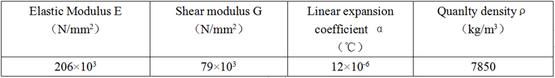
The physical properties of steel and steel castings are shown in Table 1-6.
Physical properties of steel and steel castings Table 1-6
The deflection of crane beam, floor beam, roof beam, work platform beam and wall frame parts should not exceed the allowable values listed in Table 1-7.
Allowable values of deflection of flexural members Table 1-7
| Item | Component category | Allowable value of deflection | |
|---|---|---|---|
| [νT] | [νQ] | ||
| 1 | Crane beam and crane truss (calculation of deflection by one crane with the largest weight and lifting capacity) (1) Manual crane and single beam crane (including hanging crane) (2) Light working bridge crane (3) Intermediate working bridge crane (4) Heavy-duty bridge crane |
l/500 l/800 l/1000 l/1200 |
|
| 2 | Manual or electric hoist track beam | l/400 | |
| 3 | Work platform beam with heavy rail (weight equal to or greater than 38kg/m) Work platform beam with light rail (weight equal to or greater than 24kg/m) |
l/600 l/400 |
|
| 4 | Building (house) cover beam or truss, work platform beam (except item 3) and platform board (1) Main beam or frame (including beams and trusses with suspended lifting equipment) (2) Secondary beams of plastered ceiling (3) Other beams (including stair beams) other than paragraphs (1) and (2) (4) Roof rafters Supporting corrugated iron and asbestos tile roofing without dust Supported pressed metal sheet, roofed with corrugated iron and asbestos tile Supporting other roofing materials (5) platform board |
l/400 l/250 l/250 l/150 l/200 l/200 l/150 |
l/500 l/350 l/300 |
| 5 | Wall frame parts (wind load does not consider gust factor) (1) pillar (2) Wind-resistant truss (when supported as a continuous pillar) (3) Beam of masonry wall (horizontal direction) (4) Beams supporting the profiled metal sheets, corrugated iron and asbestos tile walls (horizontal direction) (5) Beams with glazing (vertical and horizontal) |
l/200 | l/400 l/1000 l/300 l/200 l/200 |
Note: 1. l is the span of the bent member (twice the overhang of the cantilever beam and the outrigger).
2. [νT] is the allowable value of the deflection generated for all load standard values (if the arching should be subtracted from the arch);
[νQ] is the allowable value of the deflection generated for the variable load standard value.
The horizontal displacement allowable value of the frame structure: under the action of the standard value of wind load, the horizontal displacement of the top of the frame and the relative displacement between the layers should not exceed the following values.
1. Column top displacement of single-layer frame of bridgeless crane H/150
2. Column top displacement of single-layer frame with overhead crane H/400
3. Column top displacement of multi-layer frame H/500
4. Inter-layer relative displacement of multi-layer frames h/400
H is the total height from the top surface of the foundation to the top of the column; h is the height of the layer.
Note: 1. For multi-layer frame structures of civil buildings with high requirements for interior decoration, the relative displacement between layers should be appropriately reduced. Multi-layer frame structure without walls, the relative displacement between layers can be appropriately relaxed.
2. The horizontal displacement of the column top and the displacement between the layers of the lightweight frame structure can be appropriately relaxed.
The calculated lengths of the truss chord and the single rib are shown in Table 1-8.
Calculated length l0 of truss chords and single-section webs Table 1-8
| Item | Bending direction | Chord | Web | |
|---|---|---|---|---|
| Supporting slanting rod and support vertical rod | Other web | |||
| 1 | In the truss plane | l | l | 0.8l |
| 2 | Outside the truss plane | l1 | l | l |
| 3 | Oblique plane | - | l | 0.9l |
Note: 1. l is the geometric length of the component (distance between the centers of the nodes); l1 is the distance between the lateral support points of the truss chord.
2. The inclined plane refers to the plane oblique to the plane of the truss, and is suitable for single-angle steel webs and double-angle steel cross-section webs whose two main axes are not in the truss plane.
3. The calculated length of the web of the gusset plate is equal to the geometric length (except for the steel pipe structure) in any plane.
The allowable slenderness ratio of the tension member is shown in Table 1-9. The allowable slenderness ratio of the pressure-receiving member is shown in Table 1-10.
Allowable slenderness ratio of tensile members Table 1-9
| Item | Name | Structure that is subjected to static loads or indirectly subjected to dynamic loads | Directly withstand dynamic loads and structures | |
|---|---|---|---|---|
| General building structure | Plant with heavy duty crane | |||
| 1 | Truss rod | 350 | 250 | 250 |
| 2 | Inter-column support below the crane beam or crane truss | 300 | 200 | - |
| 3 | Other tie rods, supports, tie rods, etc. (except for tensioned round steel) | 400 | 350 | - |
Note: 1. In a structure subjected to a static load, only the slenderness ratio of the tension member in the vertical plane can be calculated.
2. In the structure directly or indirectly subjected to the dynamic load, the calculation method of the slenderness ratio of the single-angle steel tension member is the same as that in Note 2 to Table 2-86.
3. The slenderness ratio of the lower chord of the medium and heavy duty crane truss should not exceed 200.
4. In workshops with hard-hook cranes such as clamps or rigid magazines, the length-to-length ratio of the support (except item 2 in the table) should not exceed 300.
5. When the tension member is pressed under the combination of permanent load and wind load, the slenderness ratio should not exceed 250.
6. For trusses with a span of 60m or more, the ratio of the length of the chord and the web should not exceed 300 (withstand static load or indirect dynamic load) or 250 (directly with dynamic load).
Allowable slenderness ratio of compression members Table 1-10
| Item | Name | Allow slenderness ratio |
|---|---|---|
| 1 | Columns, trusses and rods in the skylight frame | 150 |
| Column support, crane beam or inter-column support below the crane truss | ||
| 2 | Support (except for inter-column support below crane girders or crane trusses) | 200 |
| A member for reducing the slenderness ratio of the pressed member |
Note: 1. The compressed web of the truss (including the space truss) allows the slenderness ratio to be 200 when the internal force is equal to or less than 50% of the carrying capacity.
2. When calculating the slenderness ratio of the single-angle steel compression member, the minimum radius of gyration of the angle steel should be used. However, when calculating the slenderness ratio outside the plane of the cross-bar member, the radius of gyration parallel to the angle of the angled steel limb can be used.
3. For trusses with a span of 60m or more, the allowable slenderness ratio of the compressed chord and the end strut should be taken as 100, and the other compressed webs can be taken as 150 (with static load or indirect dynamic load) or 120 (direct Withstand dynamic loads).
See Table 1-11 for the reduction factor of the calculated length stepped column of a single-storey building.
The reduction factor of the calculated length of the stepped column of a single-storey building is shown in Table 1-11.
| Factory type | reduction factor | |||
|---|---|---|---|---|
| Single or multiple spans | Number of columns in the longitudinal temperature section | Roof situation | Whether there is a long horizontal roof horizontal support on both sides of the plant | |
| Single span | Equal to or less than 6 | - | - | 0.9 |
| More than 6 | Roof of non-large concrete roof slab | No vertical horizontal support | ||
| vertical horizontal support | 0.8 | |||
| Roof of large concrete roof slab | - | |||
| Multiple span | - | Roof of non-large concrete roof slab | No vertical horizontal support | |
| vertical horizontal support | 0.7 | |||
| Roof of large concrete roof slab | - | |||
Note: The open-air structure with beams (such as the drop hammer workshop) can be reduced by 0.9.
See Table 1-12 for the anti-slip coefficient of friction surface in friction type high strength bolts. The pre-tension of a high-strength bolt is shown in Table 1-13.
Anti-slip coefficient of friction surface μ Table 1-12
| Method of processing the contact surface of the joint at the joint | Member steel number | ||
|---|---|---|---|
| Q235 steel | Q345steel/Q390steel | Q420steel | |
| Sand blasting | 0.45 | 0.50 | 0.50 |
| Apply inorganic zinc-rich paint after sand blasting | 0.35 | 0.40 | 0.40 |
| Red rust after sand blasting | 0.45 | 0.50 | 0.50 |
| Wire brush to remove rust or untreated clean rolled surface | 0.30 | 0.35 | 0.40 |
Pre-tension P (kN) of a high-strength bolt Table 1-13
| Bolt performance rating | Bolt nominal diameter(mm) | |||||
|---|---|---|---|---|---|---|
| M16 | M20 | M22 | M24 | M27 | M30 | |
| 8.8 grade | 80 | 125 | 150 | 175 | 230 | 280 |
| 10.9 grade | 100 | 155 | 190 | 225 | 290 | 355 |
The allowable distances for bolts or rivets are shown in Table 1-14.
Maximum and minimum allowable distances for bolts or rivets Table 1-14
| Name | Location and direction | Maximum allowable distance (take the smaller of the two) |
Minimum allowable distance | ||
|---|---|---|---|---|---|
| Center spacing | Outer row (vertical internal force direction or direct internal force direction) | 8d0 or 12t | 3d0 | ||
| Middle row | Vertical internal force direction | 16d0 or 24t | |||
| In the direction of internal forces | Member tension | 12d0 or 18t | |||
| Member tension | 16d0 or 24t | ||||
| Diagonal direction | - | ||||
| Center to component edge distance | In the direction of internal forces | 4d0 or 8t | 2d0 | ||
| Vertical internal force direction | cut edge or hand cut edge | 1.5d0 | |||
| Edge of rolling, automatic gas cutting or saw cutting | high-strength bolt | ||||
| Other bolts or rivets | 1.2d0 | ||||
Note: 1. d0 is the diameter of the bolt or rivet, and t is the thickness of the outer thinner plate.
2. The maximum spacing of bolts or rivets connected to the edge of the steel plate and rigid members (such as angle steel, channel steel, etc.) can be used as the value of the middle row.
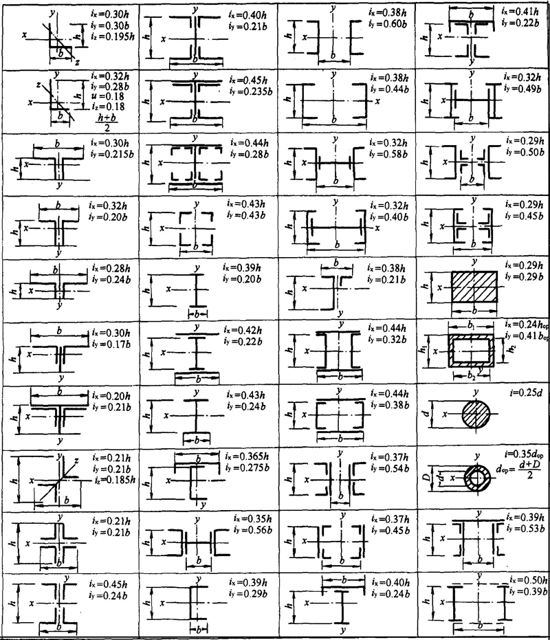
The approximate values of the radius of gyration of common sections and their combined sections are shown in Table 1-15.
Approximate values for the radius of gyration of common sections and their combined sections Table 1-15
The specifications and cross-section characteristics of circular steel pipes are shown in Table 1-16.
Circular steel pipe specifications and section characteristics Table 1-16
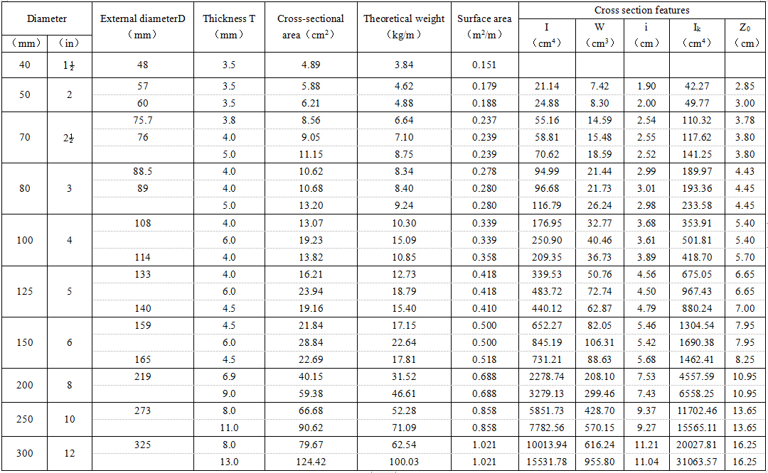
Note: I—the moment of inertia of the wool section; W—the resistance moment of the wool section; i—the radius of gyration; Ik—the torsional moment of inertia; Z0—the distance from the center of gravity of the section to the edge.