Steel structure canopy construction plan
- 29 Oct 2019
- steel structure
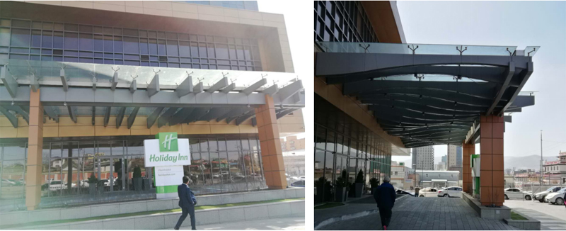
The glass canopy support structure adopts H-type steel structure. On-site construction requires steel structure installation and construction. After the installation of the steel structure is completed, the installation of the point glass system and the external aluminum plate can be carried out.
1. Support steel structure installation
The layout situation of awning steel structure is that H-type steel as the horizontal direction support structure, and the section steel is connected with the main steel structure through the embedded part.
The more detailed construction plan should be prepared for the installation of steel structures. Temporary support and stable measures must be calculated and detailed drawings should be drawn. The installation procedures must ensure structural stability and do not cause permanent deformation.
1.1 Measuring, releasing the line and checking the embedded part
1.1.2 According to the construction drawing, the angle of each positioning axis of the steel structure and the precise position of each component length are calculated and recorded as a measurement table. It is emphasized that the gages used in installation of the steel structure and the production, acceptance and the construction of the building structure should be certified to the same standard and have the same accuracy.
According to the values of the measurement table, check the positioning axis of the steel structure, the accuracy should be within 1/15000, to ensure the accuracy of the line releasing.
1.1.3 Release the steel structure installation position and auxiliary line to the nearest 0.5mm.
1.1.4 Compared to the drawing,determine the error between the actual line releasing and the noted dimension on the drawing. According to the error location and size,correct the main structure and the steel member itself to eliminate the influence of the error and ensure the installation accuracy.
1.1.5 Before installation, the position of the embedded parts and the connection with the main structure should be checked according to the results of the line releasing, to ensure the accuracy and reliability of the embedded parts.
2. Support base installation
Install the steel structure support base according to the positioning line popped on the embedded part. After the positioning is accurate, fix it firstly and then connect by spot welding.
3. H-type steel beam installation
3.1 Lift the H-type steel beam in place and keep it in a hung position.
3.2 The H-type steel beam is initially connected and fixed on the embedded parts according to the positioning position.
3.3 After adjusting the position of the steel beam, the H-beam is welded and connected with the embedded part to ensure that the welds meets the design and specification requirements.
4. Steel structure installation precautions
4.1 Before lifting on site, it should be calculated and determined to ensure the strength, rigidity and stability of the structure and components during the lifting process. Steel components installed on the same day should form a stable space system. The reaction force of the hoisting machinery and temporary support points on the main structure shall be provided to the chief designer in written form.
4.2 Leave a road with appropriate width between the installation surface and the temporary storage location for the transportation of the finished products vehicle and the lifting equipment.
4.3 During the installation process, the technical cooperation of on-site installation of the long-span steel frame,the progress of the civil works and the other structures should be done to minimize the impact on the floor structure.
4.4 Electrical welding connection process
The type of electrode should be selected according to the type of steel. Such as: If the steel is Q235b, the electrode should be E43. The electrode should be used after drying. During the welding work, the welding process card shall be compiled, and the welding measures shall be taken to ensure the quality of the weld and minimize the deformation of the internal stress and the entire steel structure.
5. Lectrical welding connections should meet the following requirements:
5.1 The electrode is required to be kept in a dry room.
5.2 Place a desiccant in the electrode box.
5.3 The moisture on the surface of the welded body was removed, and the condensation was removed with a dry cloth.
5.4 Welding is prohibited in the rain, because the water droplets on the welding surface will affect the welding rod and the welding body are not fully welded, and it is easy to generate electric leakage.
5.5 The length and height of the welding are based on the construction drawing.
5.6 During the welding process, the fire basin should be used to prevent welding sparks from damaging other finishes.
6. For all initially fixed steel structures, the installation accuracy checking should be performed. For those whose error is exceed the allowable range should be adjusted. After the secondary review, the steel structure can be finally fixed. The steel members were inspected for surface damage, repaired and painted at the damage.
7. After the installation of the steel structure is completed, corresponding protective measures shall be formulated, so that the deformation, discoloration and pollution shall not occur. Adhesives with adverse effects on the surface of steel components during construction shall be removed in time. After installation, avoid damage to the surface during cleaning.
8. Installation of point glass system
8.1 Install adapter
The adapter is installed on the H-type steel according to the glass division position, and the adapter is welded to the steel beam.
8.2 Install stainless steel claws
Connect the stainless steel claws to the adapter securely.
8.3 Install glass plates
The glass plate should be installed with the first joint.
After the glass arriving at the construction site, the surface quality and nominal size of the glass should be tested piece by piece. At the same time, a glass edge stress meter is used to perform a full inspection of the tempering situation of the glass.
The vertical transportation of the glass adopts an electric hoist temporarily fixed on the scaffold, and is vertically lifted to the installation position for positioning and installation by a vacuum suction cup.
After lifting the glass into position, place it in the compartment, align the joint with the claw hole, and tighten the joint and claw after seating.
Glass installation quality allowable deviation limit specifications and design requirements.
9. Gluing
9.1 After the glass mounting adjustment is completed, the glue is applied, and the gap between the glass plates is sealed with a weather-resistant glue.
9.2 Before injecting the glue, firstly clean the injection position by a clean and non-depilatory cleaning cloth and xylene, and use two rags to clean the position of the intended injection within half an hour before injection. The glue joint should be glued as soon as possible within half an hour after cleaning. After the time is over, it should be re-cleaned. In particular, the stains on the edges of the glass and the glue joints should be cleaned and dried. After applying the textured paper, it should be glued within 24 hours and processed in time.
9.3 The foam stick is filled in the glue joint and then glued.
9.4 When scraping the glue, the glue seam should be flattened (or concave) along the same direction on both sides of the glass panel, and the curing time of the sealant should be noted. In the gluing process, it must be ensured that the interface of the joint is smooth. If there is a bulge, it must be trimmed before the surface of the glue is solidified. Ensure that the glue line is smooth and the glue line should be horizontal and vertical,uniform in thickness and free from bubbles,no unevenness, and the bonding is firm and the appearance is beautiful after smooth after the glue is injected.
9.5 When the glue is applied every other day, the glue joint head should be cleaned firstly, and the rounded head should be removed to ensure that the two glues are tightly connected.
9.6 If a local rubber defect (such as air bubbles, hollow, broken seam, or severe surface crack) is found in the self-test, this part must be removed and cleaned and the refilled.
10. Clean
10.1 Corresponding protective measures shall be taken for steel members, claws, glass panels, etc., and deformation, discoloration, pollution, etc. shall not occur.
10.2 Adhesives with adverse effects on the decorative panels and components surface during construction shall be removed in time.
10.3 After the installation is complete, develop a cleaning plan. The damage to the surface should be avoided during cleaning.