Steel structure construction plan
- 03 Aug 2020
- steel structure
Steel structure installation e on construction site
1. Overview of on-site installation plan
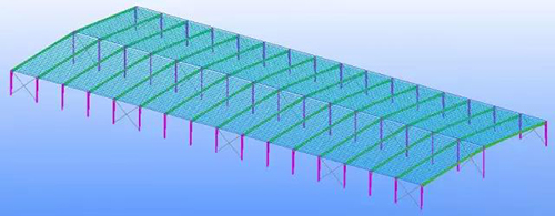
The structural form of this steel structure project is a frame, combining the form, weight, location and actual situation of the construction site, and the performance of various lifting parameters of the tower crane on site. The steel structure project is carried out by a comprehensive installation method.
1.1 On-site installation method of steel structure:
The frame columns, beams and other components of the workshop are light in weight, and the hoisting is mainly carried out by using the NK250 25t car hoist.
1.2 On-site installation sequence of steel structure:
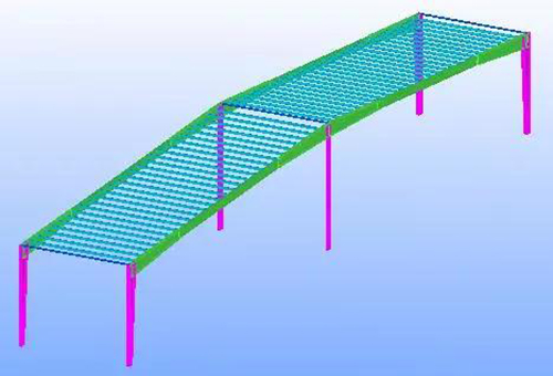
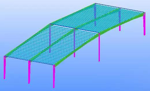
The steel structure hoisting adopts the principle of "first middle, then outer side, first column and then beam, first down and then up". A stable frame system is first formed in the middle of the factory building, and then the two steel columns and steel beam members are symmetrically installed by advancing to both ends. The sequence is shown below:
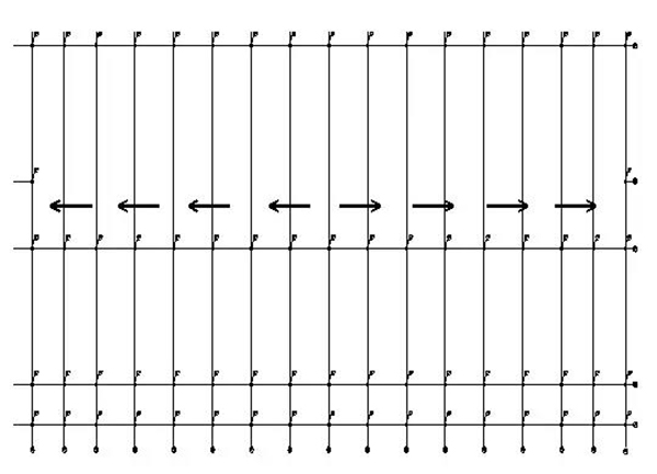
Schematic diagram of the construction sequence of a single plant (from the middle to both ends)
2. Analysis of the main installation components
The main components of this project are steel columns, steel beams, purlins, diagonal braces and other components. The steel material is Q345 B. The weight is not too heavy, as follows:
| No. | Name | Weight of each component |
|---|---|---|
| 1 | column | About 1t |
| 2 | beam | About 4t |
| 3 | purline | About 0.05t |
| 4 | bracing | About 0.05t |
3. Selection and arrangement of lifting equipment
3.1 The choice of crane
According to the site layout plan, a total of 5 steel structure workshop steel structure projects need to be installed. Combined with its lifting performance and working condition analysis, 4 NK250 25t truck cranes are deployed on site.
The main areas and uses are as follows:
| No. | lifting equipment | quantity | main application |
|---|---|---|---|
| 1 | 25t car crane | 4 | Steel component installation |
3.2 The working performance of the truck crane is as follows
The rated total lifting weight of NK250 25t truck crane is as follows (unit: T):
| length/m radius/m |
17.2 | 24.2 | 31.2 |
|---|---|---|---|
| 8 | 9.6 | 8.45 | 7.0 |
| 10 | 6.3 | 6.7 | 5.6 |
| 12 | 4.3 | 5.0 | 4.65 |
| 14 | 3.1 | 3.7 | 3.9 |
| 16 | 2.8 | 3.0 |
4. Steel structure installation process
4.1 Overall process of installation process (taking freezer as an example)
Retesting of anchor bolts → unloading of steel components → inspection of components into the field → direct hoisting of truck crane in place → temporary tightening of anchor bolts → temporary tightening of cable wind ropes → adjustment of the position and verticality of steel column axis → adjustment of steel column bolts and Fastening and welding of the column foot pressure plate → installation of the next steel column → installation of tie bars between the steel columns → forming the first stable lattice system → the steel roof truss is assembled on the ground and lifted in place by two machines to form the first steel roof truss → Symmetrical installation of columns and roof truss systems on both sides → …… → and so on → the installation is completed and the structure is accepted.
4.2 Division of steel structure installation area
This project consists of five parts: meat freezing, meat market, vegetable storage, vegetable market, and open sales area. According to the division of the construction flow section, it is divided into five areas. The specific divisions are shown in the following figure.
4.3 Overall installation sequence of steel structure
According to the overall deployment of the project, it is planned to arrange two construction teams to carry out the construction at the same time. The overall construction sequence of the five areas is as follows: Area 1, Area 2... Area 5.
For the same steel structure factory building, the steel component installation sequence is to install with the method of "reducing error, from the middle to both ends".
4.4 Installation sequence of steel structure (taking freezer as an example)
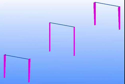
(1) Install the first row of steel columns.

(2) Install the second row of steel columns.

(3)Install the connecting beam (or tie bar) between the steel columns.
(4)Install the first steel roof truss using double cranes.
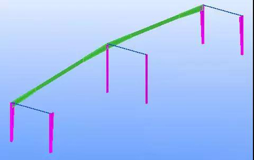
(5)Install the second steel roof truss using double cranes.
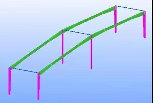
(6)Install purlins between two roof trusses to form a stable frame system.
(7) Continue to install the steel columns, connecting beams, roof truss and purlins of the next rigid frame.
(8)Continue to install the roof truss in the above order, and the support between the columns is also inserted to install.
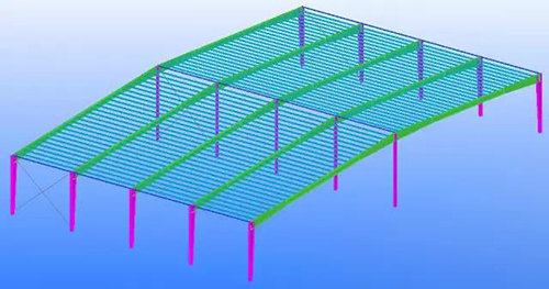
(9)Continue the installation.
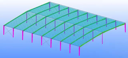
(10)The roof truss installation is completed.
4.5 columns bracing installation
The inter-column bracing and the steel column are combined with joint plate bolt connection and welding connection. The manufacturing and installation deviation of the steel column may have a greater impact on its installation. The inter-column bracing is transported to the site as a whole after assembly and assembly in the factory. To install. The column bracing is lighter in weight and can be lifted by a 25-ton truck crane.
The hoisting sequence of cross-type column bracing is as follows:
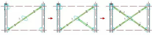
When hoisting, it is divided into three monomers 1, 2, and 3 to be hoisted separately. The three monomers are all plane truss structures, and the hoisting is integral hoisting. When installing, first install 3, then pull the hoist to the steel column for temporary fixation, then install 1, connect the nodes of 3 and 1, remove the hand hoist, and finally install 2. The three monolithic trusses hoisted integrally adopt 4T hoisting of 25T truck crane.
4.6 Installation of roof beam
(1) Anti-deformation measures for hoisting too long steel frame
The longest steel frame is 56 meters long. In order to prevent the deformation of the longer steel frame during the lifting process, the lifting of the longer components adopts the method of two-machine lifting and four-point lifting. Four-point lifting is synchronously stressed at four points during lifting. The point distance is guaranteed to be about 6 meters, so that the steel frame can achieve uniform stress during the lifting process, and the design size can be maintained during the lifting process, which meets the requirements of the specifications. The details are shown below:
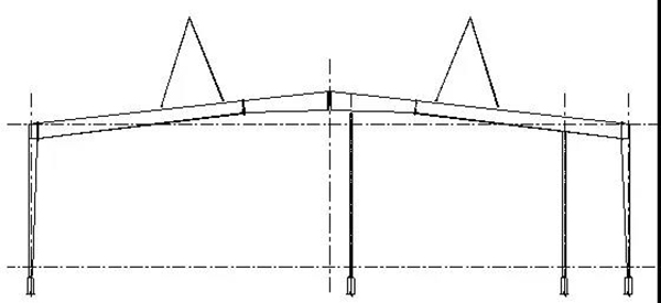
Schematic diagram of hoisting the steel roof truss
(2) Hoisting machinery and construction measures
When hoisting the steel beam of the roof truss, a hand hoist is connected in series on the steel wire rope to adjust the posture of the steel beam in the air.
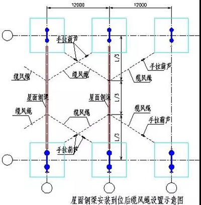
After the roof steel beams are hoisted in place, the relevant roof steel purlins should be connected before loosening the hooks to form a stable structure of the space frame. If the roof steel purlin cannot be installed before the hook is loosened, in order to prevent the steel beam of the roof truss from being twisted, a cable wind rope should be installed. The cable wind rope is fixed to the steel beam of the roof truss before hoisting. There are a total of four cables, and the pulling position is 1/3 of the length of the steel beam. The cable wind rope is Ф13.5mm, and it is tightened with 1T hand hoist. After the connecting beam between the main steel beams of the roof is installed, the cable wind rope can be removed.
Because the steel column is installed with a certain allowable deviation, and the roof truss beam and the steel column are connected by high-strength bolts, when installing, when the hoisting is in place, first connect one end (but not fasten), if the other end can be directly connected, then Directly connected in place, if the deviation is too large, the steel column cable wind rope should be adjusted, and the height spacing of the roof beam should be adjusted, but the deviation of the steel column itself should meet the requirements of the specification.
Roof and wall system construction
1. Purlin installation
1.1 Ground transportation of purlins
From the raw material storage site, use trucks or flatbed trucks to transport the purlins to the crane, and then bind them with wire ropes.
1.2 Vertical transportation:
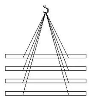
The bundled purlins will be hoisted to the installation site by using on-site cranes. Because the purlin has a small single weight and is a linear rod, it is easy to bind. The main time-consuming when hoisting is hooking and falling. To increase the installation speed, the method of one hook and multiple hooks is used to improve work efficiency, as shown in the figure.
1.3 Overall order of purlin installation
The installation order of purlins and purlins bracket is as follows:
Purlin bracket installation → Purlin installation → Roof system installation
Installer
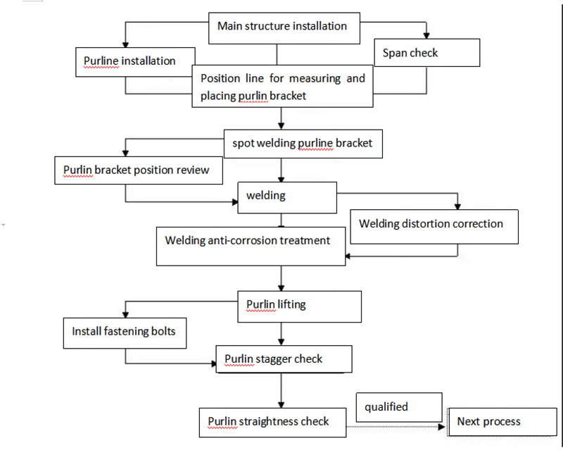
Purlin and purlin bracket installation process
1.4 Purlin installation and positioning
⑴According to the production and installation standards of the roofing of this system and the measurement data handed over by the steel structure construction unit, determine whether the height difference of each purlin positioning point needs to be adjusted. The quantity does not exceed three pieces, and welding treatment is adopted between the pieces. The entire purlin surface is basically smooth according to the installation standard. The pads must be derusted before installation, and the coating treatment is in accordance with the purlin coating requirements.
⑵The positioning and installation of the metal roof panel system is mainly divided into the purlin pallet positioning and steel support positioning, and its installation should be strictly in accordance with the approved design drawings. The total station and theodolite are used to pay off according to the design requirements, and the positioning wire is installed on the steel support.
1.5 Purlin installation
⑴ Purlin positioning
Purlins are welded to the steel structural beams and bracing. The purlin positioning method is as follows: according to the purlin distance and the axis, the intersection line of the purlin and the steel structure beam (the positioning line popped out by the pay-off) is determined, and this intersection line is the installation line of the purlin bracket.
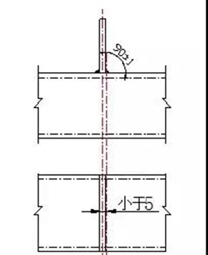
⑵ Purlin bracket installation
As shown in the figure below, after the purlin bracket is positioned, the angle between it and the plane of the wing of the steel beam must be 90°±1°, and the position deviation should be within 5mm. During the welding process, measures to reduce deformation should be taken. Spot welding should be performed symmetrically, the angle of the purlin bracket should be checked, and the welding should be done after passing the test. If it fails, the angle should be corrected. Spot welding should be firm. The electrode diameter is 4mm and the electrode type is E5016. The current should be appropriate during welding. No pores and cracks, no undercuts or nodules should appear after the weld is formed. The weld size should meet the design requirements, the welding wave should be uniform, and the weld formation should be beautiful.
(3) anti corrosion treatment
After welding, anti-corrosion treatment shall be carried out on the weld and its surrounding areas. The anti-corrosion material shall be the paint meeting the design requirements, and two coats of paint shall be applied. Before anticorrosion, the coating and dirt on the weld surface shall be removed.
(4) purlin fixing
All purlins in the project are connected with purlin bracket bolts. After the purlins are lifted in place, it is necessary to check whether the top surface of the purlins being installed is flush with the top surface of adjacent purlins installed. If the purlins are not flush, adjustment shall be made. When the height difference of the top surface of the adjacent purlins is within 2mm, the bolts can be tightened. During the installation, the top surfaces of the two adjacent purlins should be adjusted to be consistent as far as possible.
2. Gutter installation
2.1 Installation of gutter bracket
(1) small section steel is used as gutter bracket in this project;
(2) install the gutter bracket according to the designed spacing, and check whether the top elevation of the support is consistent.
2.2 Gutter installation
(1) sectional gutter splicing
Before butt joint of gutter, the cutting edge shall be polished. During butt joint, the gap between butt joints shall not exceed 1 mm. Spot welding shall be carried out every 10 cm to confirm that the welding requirements are met. The type of electrode shall be determined according to the base metal. The weld is formed in one pass. In order to speed up the installation speed of the gutter, two or three gutters can be assembled on the ground, and then lifted to the installation position or the nearest position with a 16 ton crane. This can not only improve the docking quality of the gutter, but also greatly improve the working efficiency.
⑵In order to control the deformation caused by welding, the method of spot welding first and then segmented welding must be adopted. After welding, discoloration will appear in the range of 20 mm on both sides of the weld, which should be removed by grinding and polishing with cloth grinding wheel immediately.
(3) after the gutter is installed, the bottom shall be flat without ponding.
2.3 Gutter water test
After the gutter is installed, the gutter should be filled with water to check whether the gutter is leaking. After the gutter is not leaking, check and accept it. In case of leakage, the leakage shall be repaired by welding again, polished, and repeated leak proof test until qualified.
3. Installation of profiled steel plate for roof and wall
The roof panel of the project is planned to adopt 100 thick lined polyurethane color steel sandwich panel, and the wall panel is to adopt 75 thick lined thermal insulation polyurethane color steel plate.
3.1 basic requirements:
(1) the plate should be handled with care to avoid collision. It is forbidden to mop the floor to avoid damaging the plate.
(2) first determine the starting point of installation, which is determined according to the design drawings and site conditions, generally from one side to the other side. During installation, the datum line should be snapped to avoid accumulated error.
(3) determine the installation direction, and install from one end to the other after ejecting the datum line.
(4) the edge lap of two parallel surfaces should be straight to ensure the indoor beauty. The joint direction of the panel should avoid the main angle of view. When the main wind direction is obvious, the lap edge of the panel should face the downwind direction.
(5) the sandwich panel shall be reliably overlapped on the bracket member, and the lap length shall meet the design requirements and shall not be less than the provisions in the following table.
Lap length of profiled steel sheet on supporting member (mm)
| Item | overlapping length | |
|---|---|---|
| Section height>70 | 375 | |
| Section height≤70 | Roof slope<1/10 | 250 |
| Roof slope≥1/10 | 200 | |
(6) the allowable deviation of profiled steel plate installation shall meet the requirements in the table below.
Allowable deviation of profiled steel plate installation (mm)
| Item | Allowable deviation | |
|---|---|---|
| roof | Parallelism of cornice and roof | 12.0 |
| The perpendicularity of the corrugated line of profiled steel plate to the ridge | L/800, and should not be greater than 25.0 | |
| The ends of two adjacent profiled steel plates of the cornice are misaligned | 6.0 | |
| The maximum wave height of the rolled steel plate | 4.0 | |
| Note: L is the length of the half slope or single slope of the roof; | ||
3.2 Installation method:
(1) Set up a walkway on the purlin to ensure construction safety and construction progress.
⑵ When installing, use a crane to hang the board to the roof. Lifting straps must use flexible straps such as nylon straps or cloth straps, and steel straps must not be used. Protective wooden strips should be inserted between the packaging and the sling or packaging to prevent the board edge from deforming.
(3) Before installation, the surface of the board should be cleaned and dried, and then check whether there is residue on the board surface, such as cleaning the mixture with a cleanser and water. And wipe the surface moisture with a dry cloth.
⑷ The laying direction of the board must be laid against the dominant direction. During the installation of the roof slab, the wire must be stretched at any time to prevent accumulated errors.
⑸ During the roof panel installation process, the roof cover and waterproof plug must be installed at the same time.
⑹ The slab is more sensitive to concentrated load, so during the construction of the roof color board, the construction personnel should not gather together to avoid local damage of the board caused by the concentrated load.
⑺ When installing the roof panel, it should be installed while hoisting and transporting. At least, the board on the roof of the hoisting and transporting must be installed on the same day. Any board that has not been installed on the day must take corresponding measures to prevent falling.
(8) Quality requirements: The color steel plate is correct in size, the surface is clean, there is no noticeable unevenness and folds, the joint is straight, the vertical and horizontal laps are all straight, the joints are even and neat, tightly warped and error-free drilling holes.
3.3 Installation of roof plugs and roof ridge boards:
(1) Locate the starting reference line of the first ridge board, and determine the installation control line of the ridge plug and the two sides of the ridge plug in the installation direction.
⑵ Install the roof plug plate, and the contact part between the plug plate and the molding plate is coated with waterproof glue, and then install, seal the plug with waterproof glue to prevent leakage, and install the subsequent plugs in sequence.
(3) Install the first roof board, and install the first roof board according to the starting reference line and control line to adjust the positioning. Measure the positioning plate of the bent water baffle on the ridge board, cut it with scissors, fix the ridge board on the profiled board with the specified riveting top, seal the fixing member with waterproof glue, according to the bent Fold the positioning line and bend the positioning line to bend the water retaining plate.
3.4 Installation of flashing, wrap angle, expansion joint cover:
(1) Set the starting reference line of the first block, and determine the control lines on both sides of the board along the installation direction.
⑵ Install the first piece, install the second plate according to the reference line and control line to adjust the positioning, fix it on the fixing plate, and seal the fixing piece with waterproof glue to prevent leakage.
(3) Measure the overlapping positioning line between the second board and the first board on the first board, apply waterproof glue to the overlapping part of the board, install the second board to adjust the positioning, fix the fixing parts and apply waterproof glue Seal, install the second board and subsequent board in turn.
3.5 Wall panel installation
Wall panel installation process: wall panel installation → wall color plate accessories installation → wall project finishing
Key technological practices:
a. Before installing the wall panel in construction, first set up the sliding shelf, which is suspended.
b. Consider a lap seam in the longitudinal direction. The lap seam should be considered at the position of the purlin. The lap length should not be less than 100MM, and the mouth of the lower plate should not exceed the upper edge of the purlin.
c. Lines must be drawn before installation to ensure that the board and screws are vertical and accumulate errors.