Steel structure processing equipment
- 09 Mar 2020
- steel structure
1.main processing equipment of steel structure workshop
| No | Mechanical Equipment Name | Type | Quantity | Notes |
|---|---|---|---|---|
| 1 | Multi-head flame cutting machine | 1 | own | |
| 2 | Semi-automatic cutting machine | 3 | own | |
| 3 | Automatic assembly machine | 2 | own | |
| 4 | Automatic door type welding machine | 3 | own | |
| 5 | correction machine | 2 | own | |
| 6 | End surface sawing machine | ST6090 | 2 | own |
| 7 | 3D CNC Drilling Machine | JNF1000 | 1 | own |
| 8 | Automatic locking machine | ASL-35TW | 2 | own |
| 9 | Purlin molding production line | RC400 | 1 | own |
| 10 | Automatic submerged arc welding | 3 | own | |
| 11 | CO2 Gas shielded welding machine | 30 | own | |
| 12 | AC and DC welding machine | 20 | own | |
| 13 | Shot blasting machine | 1 | own | |
| 14 | Beveling machine | 1 | own | |
| 15 | CNC trimming machine | 1 | own | |
| 16 | CNC Folding Machine | RS25070K | 1 | own |
| 17 | Rocker drilling | 1 | own | |
| 18 | 400 Ton Hydraulic Press | 1 | own | |
| 19 | Ultrasonic flaw detector | 3 | own | |
| 20 | 10TGantry crane | 1 | own | |
| 21 | 30 TBridge crane | 1 | own | |
| 22 | 20TBridge crane | 1 | own | |
| 23 | 10 TBridge crane | 1 | own | |
| 24 | 5 TBridge crane | 1 | own | |
| 25 | Automatic paint spraying machine | 2 | own |
Notes:The number of the above machines can be controlled according to the production scale.
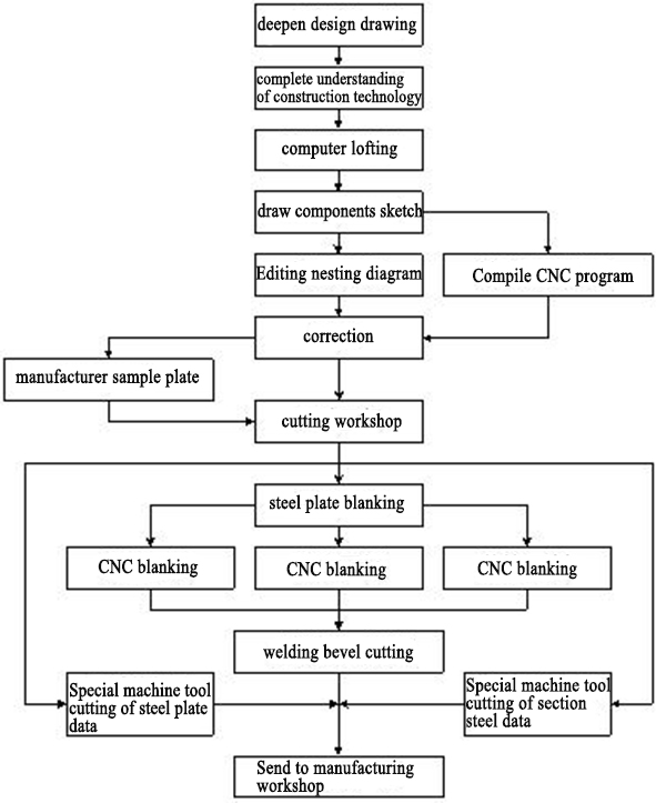
2. Production Process of main steel structure
2.1 Processing production segmentation
2.1.1 Processing segmentation principle
Considering whether and how to segment by combining raw material specifications, transportation restrictions, and final installation options.
| No | Segmentation principle(influence factors) |
|---|---|
| 1 | Equipment lifting ability of factory |
| 2 | Factory inspection equipment, inspection control points, inspection of concealed welds, etc. ; |
| 3 | Combine the welding process to ensure the down welding, flat welding and vertical welding positions of the components and nodes after being turned upside down and hoisted; |
| 4 | The practice of segmented interfaces (cutouts and bevels); |
| 5 | Plate parts setting of segmentation connection; |
| 6 | The splitting principle of on-site lifting and segmentation: the determination of vertical or horizontal assembly and the practice of segmented interfaces to avoid back welding. |
2.1.2 Component segmentation
In general steel structure engineering, the steel columns not exceeding 15 meters do not need to be produced in segmentation. Steel beams are assembled, spliced and hoisted after being transported to construction site.
2.2 General manufacturing process measures of steel structures
2.2.1 Steel correction
| No | Steel Correction |
|---|---|
| 1 | For the steel to be processed, it should be checked before processing for any harmful deformation (such as partial winding, bending, etc.). According to the actual situation, mechanical cold correction or heating correction (wire heating, point heating) is used. When using heating correction, it should be noted that the thermal correction heating temperature does not exceed 820 ° C. Water cooling is strictly prohibited during the correction. |
| 2 | Carbon structural steel should not be cold-corrected when the ambient temperature is lower than -16 ° C, and low alloy structural steel is lower than -12 ° C. |
| 3 | The surface of the corrected steel should not have obvious concave surface or damage, and the depth of the scratch should not be greater than 0.5mm, and should not be greater than 1/2 of the negative allowable deviation of the thickness of the steel. |
| 4 | The allowable deviation after the correction of steel shall comply with the provisions in the "Code for Acceptance of Construction Quality of Steel Structure Engineering". |
2.2.2 Lofting
| No | Lofting |
|---|---|
| 1 | The steel tape measure, theodolite, and other measuring tools used for lofting, cutting, production, and acceptance must pass the inspection by the city, ministerial or higher measurement unit. The measurement should be based on a qualified steel tape measure (100m), and the size of the corrigendum should be attached for verification with the supervision and installation company. |
| 2 | All components shall be manually scaled up by 1: 1 or simulated by computer in accordance with the detailed design drawings and manufacturing process requirements, and the geometric dimensions of all components shall be verified. If an error is found that needs to be changed, the design change notice issued by the original design company must be obtained, and it must not be modified without authorization. After passing the lofting inspection, the necessary angles, notches, production templates and tire frame templates must be made according to the process requirements. |
| 3 | Marking tolerance requirements: datum line, hole distance position --- allowable deviation ≤0.5mm. External dimensions of parts --- Allowable deviation ≤0.5mm |
| 4 | The baseline, centerline and inspection control points shall be marked after the scribe. Do not use a tool such as a chisel when making a mark. The depth of a small number of sample punches should not be greater than 0.5mm, and no permanent scribe marks should be left on the steel plate |
2.2.3 Butt Joint of Raw material
| Item | Butt joint requirements |
|---|---|
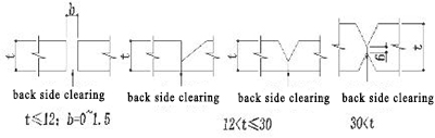
| Butt joint of steel plate | Butt joint weld grade: level one, butt joint groove form is shown in the below figure:
The bevel processing is performed by semi-automatic flame cutting and polished to reveal a good metallic luster. All cutting defects should be repaired and allowed to be assembled and welded; the wrong side of the assembly butt joint should not be greater than t / 10 and ≤ 2mm; 100% UT inspection is performed 24 hours after the butt weld is welded, and the welding quality level is first-class. |
| Butt joint of section steel | Need to be welded through and inspected. The connection length is greater than or equal to 500mm, and the nearby gusset plates and hole groups should be staggered by 100mm. Whether the welding seam is smooth or not depends on the installation situation. Plate steel beams are cut from the entire plate in principle. If it is allowed, the butt joint on the upper and lower wings of the beam within 1/3 of the beam end should be avoided. The butt joint welds of the upper and lower wing plates and the web plate should not be set on the same cross-section. They should be staggered by more than 200mm from each other. The hole groups of the stiffeners should be staggered by more than 100mm, and can only be assembled after being jointed separately. |
2.2.4 Cutting and planing processing
1)Selection of cutting tools
| Item | Tools | ||
|---|---|---|---|
| Flame cutting machine | Semi-automatic flame cutting machine | Shearing machine | |
| t>9mm part plates | √ | √ | |
| t≤9mm part plates | √ | ||
2)Before cutting, the oil, rust and moisture on the surface of the base metal should be removed; after cutting, the surface of the gas cutting should be smooth and free of cracks, slag and gas samples should be removed, and the cutting edges should be polished.
3)Tolerance requirements for gas cutting:
| Item | Allowable tolerance |
|---|---|
| Components length | Length ±1.0mm |
| Components width | Flange and web plate of plate H type steel:width ±1.0mm parts plate:width±1.0mm |
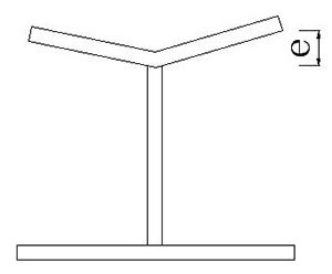
| Non-vertical degree cutting surface e | t≤20mm,e≤1mm;t≥20,e≤t/20且≤2mm |
| Cut notch depth | 0.2mm |
4)Lofting cutting process
2.2.5 bevel process
1)The bevel processing of components is processed by automatic (semi-automatic) flame cutting machine or milling machine. The groove form shall meet the requirements of welding standard drawings.
2)The groove surface should be free of cracks, slag inclusions, delamination and other defects. After the processing, the slag and burrs on the bevel surface should be removed, and the rust should be removed to reveal a good metallic luster. Derusting can be treated with grinding wheels and shot blasting.
3)The allowable deviation of bevel processing shall meet the requirements of the following table:
| Item | Allowable tolerance |
|---|---|
| Bevel angle | ±5° |
| Beveled edge | ±1.0mm |
| Groove surface cut pattern depth | 0.3mm |
| Local notch depth | 1.0mm |
2.2.6 Welding and correction
1)Before assembly, check whether the number, material, size, quantity and processing accuracy of the assembly parts meet the requirements of drawings and processes, and after confirmed,the assembly can be carried on.
2)The assembly platform and tire frame should meet the accuracy requirements of component assembly, and must have sufficient strength and stiffness, and can only be used after acceptance.
3)Assembly of components shall be carried out in accordance with the process flow, and rust and oil stains within 30mm of the four longitudinal welds of the plate H-type steel shall be cleaned up. The loose oxide scale should be cleaned up at the assembly place of the stiffener.
4)Concealed surfaces that cannot be painted after assembly should be cleaned and painted in advance.
5)After the components are assembled, self-inspection and mutual-inspection should be carried out. Only when they are correct,can be they submitted to the special inspection personnel for acceptance. If problems are found during the inspection, they should be reflected in time and repaired and corrected after the method to be processed is determined.
6)assembly accuracy of components
| No | Item | Sketch | Allowable deviation(mm) |
|---|---|---|---|
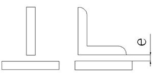
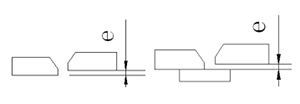
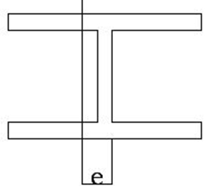
| 1 | T-type joint gap e |
|
e≤1.5 |
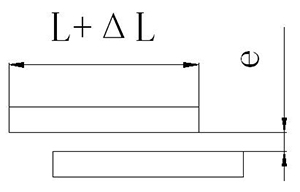
| 2 | Lap joint gap e length△L |
|
e≤1.5 L:±5.0 |
| 3 | Butt joint Dislocation e |
|
e≤T/10 and ≤3.0 |
| 4 | Butt joint gap e(without liner) |
|
-1.0≤e≤1.0 |
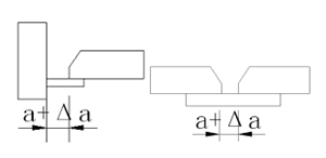
| 5 | Root opening gap△α(with liner at back) |
|
Submerged arc welding:-2.0≤△α≤2.0 Manual welding, semi-automatic gas shielded welding:-2.0≤△α |
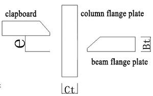
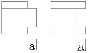
| 6 | Dislocation of clapboard and beam flange e |
|
When Bt<Ct:Bt≤20 e≤Bt/4;Bt>20 e≤5.0 When Bt<Ct:Bt≤20 e≤Bt/4;Bt>20 e≤5.0 |
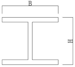
| 7 | Shape of combined H-steel |
|
-2.0≤△b≤+2.0 -2.0≤△h≤+2.0 |
| 8 | End deviation of welding assembly components α |
|
-2.0≤α≤+2.0 |
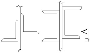
| 9 | Type steel dislocation |
|
△≤1.0(joint part) △≤2.0(other parts) |
| 10 | H steel web plate offset e |
|
e≤2mm |
| 11 | Angular deformation of H- steel flange plate |
|
Joint part e≤b/100 and≤1mm Non-joint part e≤2b/100 and ≤2mm |
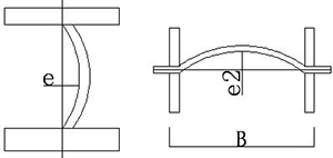
| 12 | Web plate bending |
|
e1≤H/150 and e1≤4mm e2≤B/150 and e2≤4mm |

7)Correction
| Correction method | Correction measures | |
|---|---|---|
| Mechanical correction | Generally, it should be performed by mechanical equipment at normal temperature. For example, the unevenness of the steel plate can be leveled by a seven-roller leveler.The angular deformation after welding of H-beam can be corrected by flange plate correction machine. However, the surface of the corrected steel should be free of severe dents and other damage. | |
| Flame correction | Flame correction is that the material is heated at a temperature of about 850 ° C (Q345 material). Do not use cold water to cool it. During hot processing, it is carried out in the red hot state (900-1000 ℃), and the processing should be finished before the temperature drops to 800 ℃, and the blue brittle zone (200-400 ℃) must be avoided. Be careful not to damage the base material during heat correction. |
2.2.7 Hole making
1)High-strength bolt holes and ordinary bolt holes are processed by CNC drilling machine;
2)The anchor bolt hole are processed by scoring rocker drilling machine after underline. The deviation of the scoring hole position should be controlled within 0.5mm. The hole center is marked with a sample punch and the hole size should be marked. After the line is drawn, the line must be checked to confirm that it is qualified and allowed to be processed.
3)After drilling, burrs and flashes around the hole should be cleaned.
| Item | Allowable deviation | |
|---|---|---|
| Hole wall surface roughnessRa | Ⅰ-type hole | ≤12.5μm |
| Ⅱ-type hole | ≤25μm | |
| Ⅰ-type hole diameter allowable deviation | φ10~18 | 0~+0.18 |
| φ18~30 | 0~+0.21 | |
| φ30~50 | 0~+0.25 | |
| Ⅱ-type hole allowable deviation | diameter | 0~+1.0 |
| roundness | 2.0 | |
| verticality | 0.03t and≤2.0 | |
| Allowable deviation of hole distance between bolts in the same group | ≤500 | ±1.0 |
| 501~1200 | ±1.5 | |
| Allowable deviation of end hole spacing between two adjacent groups | ≤500 | ±1.5 |
| 501~1200 | ±2.0 | |
| 1201~3000 | ±2.5 | |
| >3000 | ±3.0 | |
| Instructions:1、All bolt holes connecting the connecting plate with a rod in the node are a group; 2、The bolt holes of joint on one side of the splicing plate are a group; |
||
2.2.8 Processing of friction surface of high-strength bolt connection plate
| No | Friction surface processing | |
|---|---|---|
| 1 | Processing machinery and parameter selection | Small blasting machine; The shot uses 1 ~ 1.5mm high hardness ore; The capacity of the air compressor for sand blasting is 6-20 m3 / min, and the spraying force should be above 0.5MPA. |
| 2 | Processing | During spraying operation: the spraying angle is 90 ° ± 45 °, and the spraying distance is 100-300. The traveling speed should not be too fast. Pay attention to the embroidery of the dead corners on the reverse side of the component. The anti-slip friction coefficient must reach 0.45 (Q235), 0.50 (Q345) or more. The abrasives used must be labeled on the packaging bags to prevent the frictional surface of the abrasives from being mixed and processed. The plastic film should be wrapped on surface to prevent oil and damage. |
| 3 | Inspection | After the friction surface treatment and before the construction of the high-strength bolted steel structure, the anti-slip coefficient of the surface of the steel structure should be re-inspected to ensure the construction quality of the high-strength bolts. Each 2000T is a batch.If the quantity is less than 2000T, then it will be one batch. There are three sets of friction pieces processed at the factory. As a self-inspection, there should be three sets of friction pieces when the component leaves the factory. As a re-inspection at the construction site, the minimum value of the anti-slip coefficient test should be greater than or equal to the design requirements. The test specimens for the anti-slip coefficient test shall be high-strength bolts of the same material grade, the same friction surface treatment method, the same batch manufacturing, the same transportation conditions, and the same store conditions and same performance level with the steel structure they represent. |
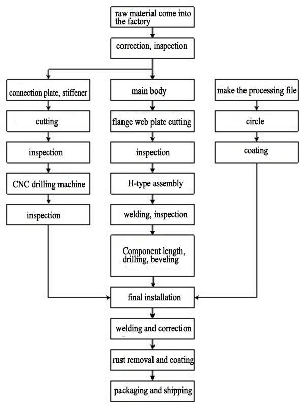
2.3 H-type steel processing technology
2.3.1 Processing flow of welding H-type steel beam
2.3.2 Production processing of welding H-type steel beam
| No | Process | Production processing | Diagram |
|---|---|---|---|
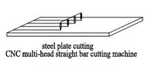
| 1 | Components cutting | 1)The components cutting are produced by CNC plasma, CNC flame and CNC straight bar cutting machine; 2)The flange and web plate of the profiled steel are cut vertically by a straight bar cutting machine at two sides at the same time, and the irregular components are cut by the CNC cutting machine. 3)The length of the flange and web plate of the H-type steel will be added for 50mm, and the width does not allow the margin. When preparing the material for the workshop, add the margin according to the process requirements; |
|
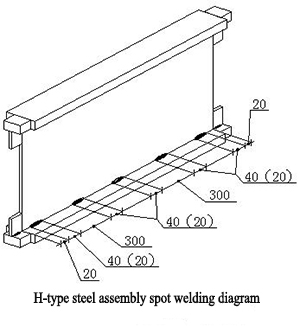
| 2 | H-type steel assembly | (1)The assembly of profiled steel can be performed by H-shaped steel assembly line assembly machine or artificial tire frame. spot welding adopts gas shielded welding. Among them, the distance between the initial welding point to the end point is 20mm. When the length of the component is short, and its length is below 200mm,the spot welds are in two points, and the position is 20mm from the end point. 2)H-type steel is not allowed to have arc abrasion during the assembly spot welding, and the undercut of spot welding is within 1mm. |
|
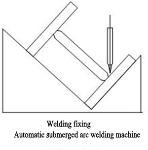
| 3 | H-type steel welding | (1)Before welding H-type steel, "T" -shaped arc starting plates and leading plates should be set at both ends of H-type steel. The length of the arc starting plate and leading plate should be greater than or equal to 150mm, the width should be greater than or equal to 100mm, and the leading length of the welds beads should be greater than or equal to 60mm. The arc-starting plate and the leading plate must be removed by gas cutting. It is strictly prohibited to remove by hammering. |
|
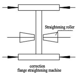
| 4 | H-type steel correction | 1)When the thickness of the flange plate is less than 28mm, the H-type steel flange straightening machine can be used for correction; 2)When the thickness of the flange plate is below 55mm, it can be corrected by using a cross column assembly line correction machine; 3)When the thickness of the flange plate is ≥55mm, use a reasonable welding process sequence to correct with the supplement of manual flame correction; the corrected surface should not have obvious concave surfaces or damage, and the depth of scratches should not be greater than 0.5mm. |
|
| 5 | H-type steel end point cutting | 1) When H-type steel has a regular cross section with a height below 1m, the AMADA or Peddinghaus section processing line are used for cutting; 2)When the H-type steel has a regular cross-section with a height of ≥1m, the semi-automatic cutting machine is used for cutting; |
|
| 6 | H-type steel hole drilling | 1)For H-type steel with flange plate width ≤ 450mm and cross-section height ≤ 1000mm, the assembly line can be used for hole processing; 2)For steel beams with a cross-section height> 1000mm, the radial drill can be used for the hole processing. |
|
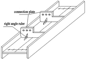
| 7 | H-type steel assembly | 1)When assembling the components, confirm that the thickness and dimensions of the parts have passed the inspection, there are no cutting burrs and gaps, and the components number, direction and size should also be checked.Check the number and specifications of the H-type steel body ready to be assembled, and confirm the partial bending and torsional deformation have been adjusted; The rust, slag, paint and moisture at welding parts or 50mm on both sides of the bevel should be removed before assembling the components. 2)Place the H-type steel body on the assembly platform;use a stone pen to draw a line on the steel component body according to the position and size of each component on the drawing. The position line includes the center line, reference line, and position line. The position lines of each components should be marked with double lines, and the positioning lines should be clear and accurate to avoid dimensional deviation due to blurred lines. |
|
2.4 Welding quality control measures
2.4.1 Welding deformation control
1)Welding deformation control
a. Use reasonable welding sequence to control deformation
For butt joint, T-joint and cross joint bevel welding, when the workpiece placement conditions are allowed or easy to turn over, it is advisable to use double-sided bevel symmetrical sequentially welding;
For double-sided asymmetric bevel welding, the order of welding should be: welding the partial welds on the deep bevel side firstly, then the shallow bevel side , and finally welds all the deep bevel side weld;
Jump welding method should be adopted to avoid localized heating of the workpiece
Weld the middle firstly and then both sides;
Weld rods with high stress firstly and then rods with low stress;
Weld the tension rod firstly and then the compression rod;
b. In the case where the joint form, weld arrangement and welding sequence are determined, a welding method with a relatively high energy density should be used, and a small heat input should be used.
c. Angular deformation should be controlled by inverse deformation method.
2.4.2 Welds inspection measures
After welding is completed, the slag on the surface and spatters on both sides should be cleaned and weld inspection shall be carried out. The inspection method shall be in accordance with DBJ08-216-95 and JGJ81-2002.
| No | Requirements for non-destructive inspection |
|---|---|
| 1 | Flaw detection personnel must have a second-level inspection certificate; |
| 2 | The visual quality inspection of third-level welds should be carried. All testing items should be carried out under the supervision of an independent tester recognized by the state; |
| 3 | Fillet welds quality is third grade.The butt welds of steel beam factory splicing quality is 1st grade, and others are 2nd grade. |
| 4 | The positions which adopts open groove full penetration weld (1) the joint part between steel beam flange plate with end plate or the flange plate joint parts; (2) after the bevel welding is applied, repair welding is required after the root of the weld is cleared The seam shall meet the requirements of 2nd grade welds; |
| 5 | Range of 2nd grade weld quality: Steel beam flange plate and end plate are spliced and welded. |
1)Visual inspection
| No | Welds visual inspection measures |
|---|---|
| 1 | All welds must be 100% visually inspected by the welder and recorded as a table |
| 2 | Cracks, slag inclusions, welding knobs, welding penetrations, arc pits, air-holes and other defects are strictly prohibited on the welds surface |
| 3 | Check welds bead size, welds fillet size, and welds throat |
| 4 | The overall dimensions of the weld shall comply with the current national standard "External Dimensions of Steel Structure Welds" |
| 5 | Defect classification of welded joints should comply with current national standards Provisions in "Welding Quality Assurance, Requirements and Defect Classification of Steel Fusion Welding Joints" |
2)Nondestructive testing
After the welding is completed for 24 hours, a flaw inspection is performed on the weld (as shown in the table below)
The allowable deviation of weld appearance defects meets the following requirements
| Inspection item | Allowable deviation of weld quality grade (mm) | Diagram | ||
|---|---|---|---|---|
| 1st grade | 2nd grade | 3rd grade | ||
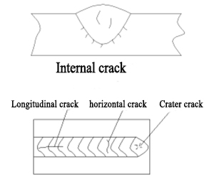
| crack | Not allowed | Not allowed | Not allowed |
|
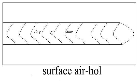
| Surface air-hole | Not allowed | Not allowed | Allowable diameter of weld length per meter≤0.4t, and≤3.0 holes 2 units, hole distance≥6times hole diameter |
|
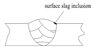
| Surface slag inclusion | Not allowed | Not allowed | depth≤0.2t length≤0.5t, and≤20.0 |
|
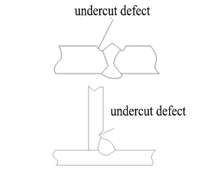
| undercut | Not allowed | ≤0.05t,and ≤0.5t; Continuous length≤100.0, and the total length of the undercut on both sides of the weld≤10% weld total length | ≤0.1tand ≤1.0, length is unlimited |
|
| Bad connector | Not allowed | Notch depth 0.05t,and ≤0.5 | Notch depth 0.1t,and ≤1.0 | |
| Not more than 1 per 1000.0 welds | ||||
| Root contraction | Not allowed | ≤0.2+0.02t and ≤1.0 | ≤0.2+0.04t and ≤2.0 | |
| Length is unlimited | ||||
| Non-full welding | Not allowed | ≤0.2+0.02t and ≤1.0 | ≤0.2+0.04t and ≤2.0 | |
| The defect total length≤25.0 per 1000.0 welds | ||||
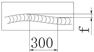
| Welds edge inconsistency f | ≤2.0 with any 300mm welds length | ≤3.0 with any 300mm welds length |
|
|
| Arc abrasion | Not allowed | Individual abrasions is allowed | ||