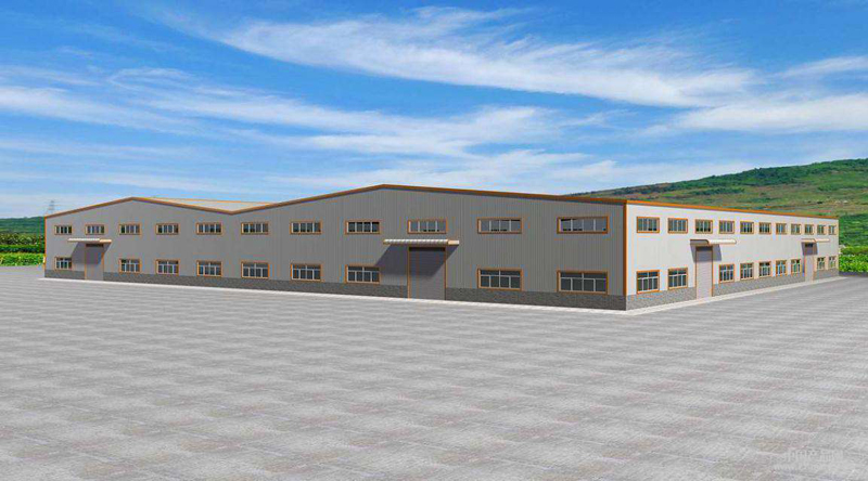
Steel Structure Warehouse Engineering
- 02 Aug 2019
- steel structure
Production and Manufacture of Steel Structures
1. Material management
1.1 Steel inspection
Building structural steels must have sufficient strength, good plasticity, toughness, fatigue resistance and excellent weldability. The following requirements must be met:
1.1.1 Brand: Steel is mainly welded H-beam. In addition to meeting the requirements of corresponding technical standards, necessary technological performance tests are needed.
1.1.2 Certificate: Steel products should be accompanied by quality certificates that meet the requirements of design documents. If there are doubts about the quality of steel products, random inspection should be carried out. The results should meet the requirements of national standards and design documents.
1.1.3 Surface quality: The depth of rust, pitting or scratch on the surface of steel should not be greater than half of the negative deviation value of the thickness of the steel; if there is a delamination defect at the fracture, it should be studied and dealt with in conjunction with the relevant units.
1.1.4 Flatness: After steel rectification, the following allowable values should be met
| Item | Allowable deviation | |
|---|---|---|
| Local Deflection Loss F of Steel Plate and Profile | L/1000 and no larger than 5.0 | |
| Thickness T | Loss of height F | |
| ≤14MM | ≤1.5MM | |
| ≥14MM | ≤1.0MM | |
1.2 Material management
1.2.1 Material entering the factory, according to the name, specifications and quantity, will be counted and stored together with the suppliers. The pound code sheet, packing list, shipping list, material certificate and qualification certificate should be checked carefully, and the quality records should be made in detail when warehousing.
1.2.2 Material stored in the warehouse should be ventilated under the cushion, upper cover and middle according to its performance and stacked according to the specifications. Material personnel should check the implementation situation at any time.
1.2.3 Material use shall be based on the principle of economy, and the section leader shall issue the quota card according to the processing budget and material loss coefficient.
1.2.4 When using materials, special materials must be specially used. In principle, materials must be used in the project.
2. Main process flow and quality control
Technological process:
Re-inspection of steel products → steel rectification → lofting stock → cutting stock → assembly forming → welding of parts → deformation correction → scribed drilling → sandblasting rust-removing paint → structural acceptance → proposed installation
2.1 Re-inspection of steel:
In order to ensure the welding quality, the chemical composition and mechanical properties of the steel used are re-checked before material preparation to ensure that the material meets the requirements of the drawings.
2.2 Steel Correction:
According to the design of this project, most of the light steel plates are thin steel plates, which are required to be straight in the welding of steel columns and beams. But because of the unevenness of the thin steel plates and the easy deformation of the shear blanking, the welding surface must be corrected.
2.3 Sampling stock:
Steel structure blanking is the first process, the project adopts the drawing blanking method, directly according to the size shown in the drawings on the steel according to the 1:1 ratio of blanking, allowable deviation is not more than 1MM.
2.3.1 The steel number and specifications of the raw materials must be known before the grade material is produced, and the quality of the raw materials must be checked. If there are scars, cracks, ash inclusion and insufficient thickness, the materials should be replaced or used with the consent of the technicians.
2.3.2 Strengthen the management of measurement, and strictly prohibit the use of measuring instruments and illegal measurement units that are not inspected, have expired or have no inspection certificate.
2.3.3 When air cutting is used for steel plate or profile, the width of the cutting seam of manual or automatic air cutting should be released:
The width of automatic gas cutting seam is 3MM
The width of manual pneumatic cutting seam is 4MM
2.3.4 In the process of sizing, the number of sizes should be recorded at any time on the sample and the sample pole. When the sizing is finished, the actual number should be recorded on the sample and the sample pole, with the words "finished" or "complete" and the date of sizing. Samples and rods are well preserved.
2.3.5 The stone brush line drawn by the size material shall not exceed 1MM in thickness and in elasticity. The allowable tolerances are as follows:
| No. | Item | Tolerance value(mm) |
|---|---|---|
| 1 | Length | ±1.0 |
| 2 | Distance between two ends of orifice | ±0.5 |
| 3 | Diagonal difference | 1.0 |
| 4 | Distance between adjacent holes | ±0.5 |
| 5 | Center spacing of two rows of holes | ±0.5 |
| 6 | Punch Point and Hole Center Distance | ±0.5 |
2.4 Cutting
2.4.1 Material specifications, models, material stove numbers and batches must be reviewed according to the requirements of drawings before cutting.
2.4.2 When cutting materials, it is necessary to cut materials strictly according to the technical personnel's submission sheet, and each piece of material must be marked with neat and clear letters with the number of drawings and parts.
2.4.3 The quantity of each component must be recorded clearly and accurately, and kept properly, so as not to be lost.
2.4.4 Before cutting, oil stain and rust on the surface of steel plate should be removed. If any defects such as cracks or slag inclusion are found in the cutting section, they should be dealt with by technicians in time.
2.4.5 The allowable deviation of the dimensions of the parts shall conform to the following provisions:
Manual Cutting ±1.5MM
Automatic Cutting ±1.0MM
Precision Cutting ±0.5MM
2.5 Assembly forming:
2.5.1 The beam and column design section steel of the project must be familiar with the drawings and the technical presentation of the technicians before assembling.
2.5.2 When assembling parts, the butt weld of flange and web should be staggered by 200 MM.
2.5.3 The length of spot weld is not less than 40MM, the interval is not more than 350MM, and the foot should not be less than 1/4 of the weld.
2.6 Component welding:
2.6.1 Gate submerged arc automatic welding machine is used for welding after assembling and forming, and the welding seam requirements are carried out according to the requirements shown in the drawings.
2.6.2 If defects such as blowhole, slag inclusion and not fully welded are found in the welding process, they should be repaired in time, and the cracks should be reported to technicians in time.
2.6.3 Make self-examination, mutual inspection and re-examination, and record accurately.
2.7 Component assembly:
2.7.1 Familiar with drawings and related technical data, and do a good job of parts inventory.
2.7.2 Lofting according to the drawings, after lofting, technical personnel should be asked to check in time before assembly can be carried out.
2.7.3 After checking and verifying the lofting, the sample is made of 1:1 sample, the cutting size is measured and recorded. Sample must be marked with obvious center line and angle line, and also with drawing number, number and quantity.
2.7.4 In the process of assembling, the number of assemblies shall be recorded in time and the original records shall be made. 2.8End plate welding:
2.8.1 Before welding, the welding procedure should be handed over. If the handover is not completed or the assembly quality is found to be not up to the requirements, the welding can be refused.
2.8.2 The arc-triggering plate must be set on the butt weld. After welding, remove the lead-off and extinguishing arc plates, and repair or clean the spatter, blowhole, arc pit, undercut and other defects.
2.8.3 Self-inspection and mutual inspection should be done well, and the quality inspectors should supervise and inspect them concretely. Welders must keep a good record of steel stamps on their products.
2.9 Deformation correction:
Welding deformation is an unavoidable problem in the manufacturing process of steel structure. Especially, thin steel plate is mostly used in this project. It is easier to cause lateral bending deformation after welding is heated, which brings some difficulties to the fabrication. After welding, the components are corrected by a straightening machine, and the web deformation is corrected by heating deformation method.
2.10 Linear drilling:
After the rectification of columns and beams, the screw hole marking process must be based on the axis of the columns and beams, draw out the dimensions of each part according to the requirements of the drawings, equip with the marking template, adopt double control, so that the dimensions of each beam and column must be consistent, the same size of beams and columns must meet the requirements of interchange, and the maximum deviation of the holes must not exceed 3MM.
2.11 Rust removal:
2.11.1 The project uses shot blasting machine for rust removal, 1.5-3MM pellets, compressed air pressure of 0.4-0.6MPA (no moisture and grease). After treatment, the surface roughness of the base material reaches SA21/2 grade and is gray-white.
2.11.2 Products with higher requirements for rust removal, such as end plates, must be qualified by the inspector before they can be assembled.
2.11.3 After steel components are assembled, the whole peening rust is removed.
2.11.4 Components after shot peening must meet the standard and must be qualified by the inspector, otherwise re-shot peening.
2.11.5 In principle, the products after shot peening and rust removal must be sprayed on duty.
2.12 Friction surface treatment:
2.12.1 In this project, steel structural parts connected by high-strength bolts are required to have a certain friction coefficient on the friction surface, which is > 0.45. Shot blasting is used to ensure that the anti-slip coefficient meets the design requirements.
2.12.2 After treatment, the friction surface should be properly protected. If there is natural rusting, the rusting period should not exceed 90 days.
2.12.3 The connection surface of high strength bolts should be smooth (unevenness 1.0MM). When there is clearance, the clearance is not more than 1.0MM. When the clearance is 1-3MM, the higher side should be grinded into a slope of 1:10, and the grinding direction is perpendicular to the direction of force.
Make anti-slip coefficient test before leaving the factory, which meets the requirements of design value, and do three pieces according to the same method for re-inspection by construction department.
2.13 For assembly:
2.13.1 Assemble each batch 10-20%, but not less than one group, or according to the design requirements and regulations.
2.13.2 All members in the assembly shall be controlled according to the construction drawings. The center of gravity of each member shall intersect at the center of the contact point and be in a completely free state. No external force shall be allowed to be forced to fix. There should be no less than two supporting points for a single member.
2.13.3 All components assembled must be checked and accepted by the Inspector-General and the acceptance record must be made. The same components should be interchangeable without affecting geometric dimensions.
2.13.4 Holes that cannot be passed according to relevant regulations shall be allowed to be repaired (hinges, grinding and scraping). If the hole is still beyond the specification after repairing, it is allowed to make holes again after welding with welding material matching the base material.
2.13.5 The quality inspector shall record the assembly of the components to be assembled.
3. Component Acceptance
Complete acceptance is carried out before arrival at the site to check the geometric dimensions of the components and the appearance of the welds. Whether the height of the welds meets the requirements of the drawings or not is strictly checked according to the national welding specifications and regulations for steel structures. Only after acceptance of the qualified components can they leave the factory.
Allowable deviation of composite component size
| Item | Symbol | Allowable deviationon | |
|---|---|---|---|
| Geometry | Inclination of flange plate | A1 | ±2 and not more than5.0 |
| The web deviates from the center of the flange | ±3.0 | ||
| Section | ±4.0 | ||
| Vertical dislocation of flange | ±2.0 | ||
| Horizontal arch of Web cross section | H/100 | ||
| Horizontal arch of Web longitudinal section | H/100 | ||
| Component Length | ±5.0 | ||
| Location | Distance from screw holes at both ends of flange to longitudinal edge of member | ±2.0 | |
| Distance from screw holes at both ends of flange to end of member | ±2.0 | ||
| Distance from the screw hole in the middle of flange to the end of member | A8 | ±3.0 | |
| Longitudinal spacing of flange screw holes | S1 | ±1.5 | |
| Longitudinal spacing of flange screw holes | S2 | ±1.5 | |
| Lateral migration of the center of the hole in the middle of the flange | A9 | ±3.0 | |
| Curvature | Bending of crane girder | C | L and ≤5(L in meters) |
| Bending of other components | C | 2L and≤9(L in meters) | |
| Upper deflection | C1 | <2L and≤9(L in meters)/td> | |
| End plate | Lateral midpoint to side hole spacing of upper flange | A10 | ±3.0 |
| Vertical Distance from Midpoint to Side Hole on the Outside of Lower Flange | A11 | ±3.0 | |
| Transverse distance between holes | A12 | ±1.5 | |
| Longitudinal distance between holes | A13 | ±1.5 | |
| Curvature(Height less than 610MM) | C | +3.0(Only concave is allowed)-0 | |
| Curvature(Height less than610-1220MM) | C | +5.0(Only concave is allowed)-0 | |
| Curvature(Height less than1220MM) | C | +6.0(Only concave is allowed)-0 | |
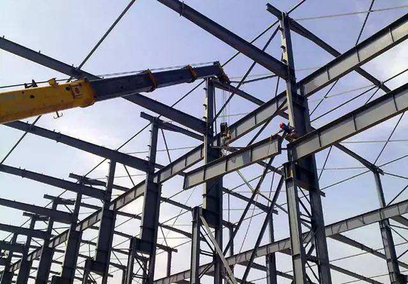
Steel structure hoisting
1. Acceptance of Steel Components
After entering the site, before installation, the quality inspection department shall organize the inspection of the products according to the requirements of the construction drawings and the specifications for construction and acceptance of steel structures. The allowable deviation of geometric dimensions of the shapes shall conform to the relevant regulations. In addition to inspecting the specifications, types and quantities of steel members entering the construction site, it is also necessary to inspect the parts prone to deformation and wear parts during transportation, and to rectify the deformed components and re-inspect them.
1.1 Pre-embedding treatment
1.1.1 Before installation of steel components, it should be handed over to the basic constructors, and the elevation, axis and bolt spacing of anchor bolts should be re-measured, and the axis, elevation and axis should be released and recorded in detail.
1.1.2 Clean up oil, mud and other debris of the embedded parts. In order to prevent the thread damage of the embedded bolt before or during installation, the necessary protection should be given to the bolt.
1.1.3 If there are errors in the elevation of the top of the column, the adjustment method of nuts is adopted in this project. A nut is added to the anchor bolt before hoisting, and the elevation can be adjusted by adjusting the nut during hoisting.
1.2 Hoisting sequence
Taking the light steel portal steel frame structure as an example, 25T automobile crane is used for hoisting. Steel columns and slender rods are installed before steel beams are hoisted. Purlins and other components are inserted and installed between them. The purlin can be transported to the approximate position by crane, and then to each room by manpower.
1.3 Steel column hoisting
1.3.1 The lifting point of steel column is obliquely lifted, that is, the lifting point is placed at 1/3 of the column length.
1.3.2 The lifting method combines the rotating method with the sliding method.
1.3.3 The verticality, elevation and axis displacement of the column are re-measured and re-calibrated.
1.4 Steel beam hoisting
1.4.1 Girder hoisting calculation should be carried out before hoisting of steel girder.
1.4.2 Ground inclined beam splicing. The steel beams are connected by high strength bolts with a_-shaped end face.
1.4.3 Steel beams are hoisted by suspension. After the beams are connected and fixed on the ground, they are hoisted by suspension of automobiles. In order to prevent the beam from swaying and collision with other components after lifting. Before lifting, the nodes near the support are tied with brown rope and relaxed with the lifting to ensure their correct position.
1.4.4 After the steel girder is hoisted in place, the first and second roof truss cables shall be fixed, and the verticality of the roof truss cables shall be corrected by the tightened cables. After calibration, purlin and wind rope are fixed to make it geometrically invariant.
1.4.5 The method of pulling wire at both ends of the lower chord and hanging weight hammer at the center of the upper chord is easy to be used for steel beam correction. After correction, the high-strength bolts at the connection are tightened to complete hoisting.
1.4.6 Steel beams in multi-storey frames should be hoisted sequentially to avoid model errors.
Installation of Main Steel Structure
1. Construction of High Strength Bolts
1.1 The purchasing of high strength bolts shall be made by a professional manufacturer approved by the relevant state departments. The grade of bolts shall be selected strictly in accordance with the design drawings and specifications of steel structures.
1.2 Before the construction of high-strength bolt connection, the anti-slip coefficient of steel structure friction surface should be re-examined. There should be three groups of friction surface parts processed in the factory when they leave the factory. As a site for re-inspection, the minimum value of anti-slip coefficient test should be greater than or equal to the design requirements.
1.3 There are two ways to fasten high strength bolt connection during installation: torsion method and rotation angle method. Torsion method uses special manual spanner to tighten high strength bolts by manpower. The angle method can be tightened by a pneumatic wrench to a predetermined initial screw value, and the final screw can be turned by a pneumatic motor or other method to achieve the requirement of bolt tension.
1.4 Bolt penetration is easy to operate and consistent. The purpose is to make the whole beautiful, and the bolt should be free to penetrate the bolt hole. For the bolt hole that can not be free to penetrate, it is allowed to be trimmed with a file or a grinding head after there is no gap between the layers around the hole diameter. The bolt should not be forced into, and the air cutting reaming hole should not be allowed.
1.5 The tightening of high strength bolt connection can be divided into initial and final tightening, which can be completed within 24H.
1.6 After tightening, hammer tapping method is used to tap bolts one by one and random sampling of the torque is carried out to ensure the installation quality.
1.7 In the construction of high-strength bolts, the fastening sequence is: first the top layer, then the bottom layer, and finally the middle layer. The bolts on the same connecting surface shall be fastened from the middle of the joint to the two ends. The fastening order of the two connecting components is: first the main component, then the secondary component.
2. Purlin Installation
2.1 When the steel frame is hoisted in place, purlin can be installed. Purlins are required to be welded on one side to the steel frame, and there are more welding on purlins installation site.
2.2 Installers fasten seat belts on fixed steel frames and arrange them on each axis.
2.3 The purlin is fixed with bolts and beams. At this time, the bolts used to connect purlins, girders and eaves support beams should not be tightened so that they can be corrected later.
2.4 When the purlin is finished, the next purlin is installed. At this time, attention should be paid to the direction of bolt installation and the direction of bolt installation at the overlap of the purlin, so that the direction of purlin overlap bolt on each axis is the same, which not only increases the beauty, but also ensures the stability of the connection between the main structure and the secondary structure.
2.5 When bolts are installed at the connection of all purlins and beams, the bolts are downward and all bolts are not tightened.
2.6 After all purlins are installed, after straightening and correction, the bolts of the secondary structures (purlins, diagonal braces, etc.) on all steel frames are further tightened to achieve structural stability.
Installation of Sub-steel structure
1. Tie rod support installation
1.1 After hoisting and checking of steel column, tie rod support between columns is installed, and scissors support between columns is installed. Horizontal support and purlin of roof are inserted and installed during installation of steel beam.
1.2 Verticality of steel beams should be checked before support installation. After the acceptance criteria are met, support should be installed and fixed immediately to form rigidity and reduce accumulated errors in the process of erection of vertical components.
1.3 After purlins are installed, purlins and tie rods on beams are installed.
1.4 The installation of stretch bar can use wooden board and bamboo ladder as secondary operation platform to accelerate the installation speed. The tension bar must be tightened to make the purlin straight.
2. Corner mounting
2.1 Corner brace should be 45 degrees with purlin and arranged along beam height.
2.2 The corners should be connected with purlins by bolts, and they should not be loosened.
Coating of Steel Structure
1. Making and painting of steel frame
1.1 After peening and rust removal, the steel frame must be qualified by the inspector before it can be coated with anti-rust paint.
1.1.1 The ambient temperature of the coating should be between 5 and 38 degrees Celsius. When there is dew on the surface of the component, it can't be sprayed, and after spraying, it can't be rained.
1.1.2 The non-coated parts specified in the technical submission shall not be sprayed.
1.1.3 In principle, the products after shot peening and rust removal must be sprayed on duty.
1.1.4 After the paint is dried, the thickness of the paint film is tested, and it must be checked to be qualified before it can enter the next process.
1.2 Topcoat can be applied on steel frames only after the anti-rust paint reaches the standard.
1.2.1 All parts of the steel frame without enclosure should be painted.
1.2.2 Painting materials of topcoat should be careful not to react unfavourably with rust-proof paint.
1.2.3 Topcoat painting is based on the intuitive standard of no leakage of the base, and it should conform to the testing standard of film thickness.
2.On-site painting of steel frame
2.1 The second painting of steel frame refers to the damage of paint film caused by transportation and hoisting after the steel frame is out of the factory and must be repaired on site.
2.1.1 The painting surface needs to be cleaned up and wiped clean.
2.1.2 After cleaning, the paint film is wooled with steel wool and other tools, and the assembly symbols are protected at the same time.
2.1.3 If the surface of the component is exposed to metal surface, the primer is first applied before the topcoat is applied. The standard requirements are designed according to the design.
2.2 Installation and repairing of steel frame.
2.2.1 Topcoat should be applied on exposed parts and fasteners of joints of steel frames.
2.2.2 The welding and burning parts during installation shall be coated with rust-proof paint and topcoat.
2.2.3 Topcoat painting is based on the intuitive standard of no leakage of the base, and it should conform to the testing standard of film thickness.
Coloured Steel Plate Installation
1. Roof color veneer installation
1.1 After the measurement confirms the rectification of the whole roof structure system, the installation of roof slabs is started.
1.2 The roof panels of this project are 820 color veneers. The stainless steel is pulled to the roof by sliding wire method. A certain number of roof panels are pre-stacked on the roof panels every certain distance for installation.
1.3 According to the layout, lay and install one by one. Fixed with self-tapping nail.
1.4 Attention should be paid to the correct orientation of the installation of roof panels, the adjacent plate buckles should be in place, nails should be vertically inlaid into the board surface, and in the vertical and horizontal direction of the board surface arranged in a straight line, buckle the waterproof groove.
1.5 Every day, iron scraps must be removed from the roof, and no overnight stay shall be allowed to prevent rust and scratches on the roof.