The Design of Light Steel Structure Workshop
- 05 Sep 2019
- steel structure
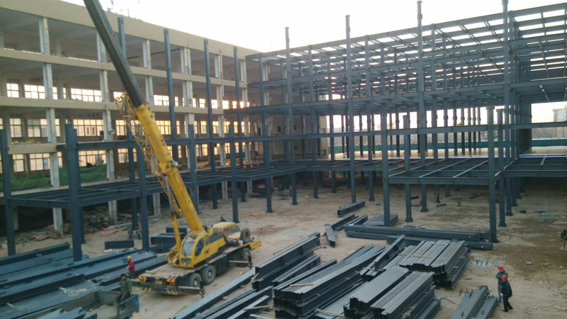
Steel structure buildings are widely used in light and heavy industrial plants because of their light weight, good seismic performance and fast construction progress. They are most widely used in steel structure buildings, especially in portal frame light steel structure factory buildings in light and heavy industrial plants. This paper briefly describes the design of portal frame light steel structure workshop, introduces its design process, and summarizes the common problems and treatment methods.
With the rapid development of light and heavy industry in China, steel structure buildings, especially portal frame light steel structure factory buildings, are widely used in light and heavy industry factories because of their light weight, good seismic performance and fast construction progress.According to "Technical Regulations for Steel Structures of Portal Frame Light-weight Buildings" CECS 102:2002 (hereinafter referred to as "Gate Regulations"), portal frame light-weight steel structure workshop mainly refers to single-span or multi-span, with light roof, light exterior wall or brick exterior wall, no bridge crane or lifting weight less than 20 t of A1~A5 workers. Single-storey steel structure factory building with bridge crane and suspension crane of no more than 3T.
1. According to the design experience, the design process of portal frame light steel structure workshop is as follows:
1.1 The span of the workshop is determined according to the conditions of capital raising and crane. The span size meets the building modulus as far as possible. Sometimes, due to the limitation of site and other factors, the above modulus can not be taken as a value, and the light steel workshop can also be completely achieved.
1.2 Column spacing size is in line with building modulus as far as possible, sometimes it can be flexibly arranged due to other factors.
1.3 The eaves height of the workshop is determined according to whether there is a crane or not and the requirement of the clearance inside the workshop.
1.4 According to the local rainfall and other factors to determine the slope of the roof of the factory building, the general value is 1/8-1/20;
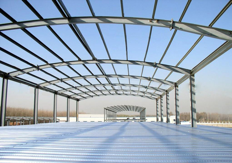
1.5 Maintenance materials of roof and wall are also determined according to professional requirements such as region or technology.
1.6 Design Load Value:
1.6.1 The roof load is determined by the maintenance material, local climate conditions and the ash accumulation on the roof. In general, the standard value of constant load is 0.3 kN/m2 for color steel plate maintenance, 0.5 kN/m2 for live load according to Gate Rules, 0.3 kN/m2 for roof uniformly distributed live load when the horizontal projection area under load is larger than 60 m2, and 0.3 kN/m2 for snow load calculation when the workshop is multi-span or high-low-span, it should be in accordance with Chapter 6.2 of Building Structural Load Code. When ash load, roof live load and snow load coexist at the same time, they should be reasonably selected according to "Code for Building Structural Load" 4.4.3 and "Gate Rule" 3.2.5.
1.6.2 Crane load. For light steel workshop with crane, the vertical and horizontal loads acting on bent brackets should be calculated. This load can be calculated in accordance with Chapter 5 of the Code for Load of Building Structures.
1.6.3 Wind load is mainly the standard value of wind load, the shape coefficient of wind load and the variation coefficient of wind pressure height. This load can be calculated in accordance with the relevant chapters of "Code for Load of Building Structures" and "Gate Rules".
1.6.4 Other loads, according to the author's design experience, are mainly roof beam suspension crane load, roof beam ventilation skylight load, column side pipe bracket load and so on. The roof beam suspension crane load can be divided into dead and live loads at the roof beam where the suspension crane acts; the roof beam ventilation skylight load can be divided into dead, active and Phoenix loads at the joints of the skylight and the roof beam; the column side pipeline bracket load can be divided into dead and live loads at the column side bracket and the column joint.
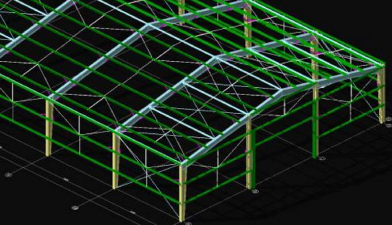
2. Design of Rigid Frame Components
2.1 According to the "Gate Rules" 4.1.4 factory building column footings can be designed as articulated or rigid joints. When the column base is articulated, the column can be designed as a variable cross-section column according to the force acting on the structure. The variable cross-section column can make the outer side of the column flat, and the positioning axis of the column can be centered at the lower end (smaller end); when the column base is rigidly connected, the column should be made into a column with equal cross-section, and the positioning axis of the column should be determined according to the height of the upper column and the distance between the crane edge and the inner edge of the upper column. At this time, the axis will not be at the center line of the column section.
2.2 Selection of component materials. Q235 and Q345 are often selected. Q235 is suitable for stability control and Q345 is optional for strength control. According to Chapter 3.3 of the Code for Design of Steel Structures, boiling steel can not be used in some parts of Q235 steel, and B, C and D steel should be selected appropriately according to local climate conditions for welded components requiring fatigue checking.
2.3 Column section is estimated by slenderness ratio. Usually, it is estimated by 50 < lambda < 150, and its value is about 80. Columns and beams are rigidly connected. The section of beams can be designed according to the force inclusion diagram. When there is a single span and no column in the middle, the section is divided symmetrically according to the span from 0.25-0.50- 0.25. The section of 0.25 at both ends is changed, and the section of 0.50 in the middle is equal, so that the design can give full play to the force performance of the section of beams and reduce the number of columns. The steel consumption can reduce the project cost; the height of the beam section is generally chosen between 1/20~1/50 of the span. When the flange width is determined according to the spacing of lateral braces between beams according to the l/b limit, the complex calculation of the overall stability of the steel beam can be avoided. This design method is relatively simple. After determining the height of the section and the width of the flange, the thickness of the plate can be avoided. It can be estimated according to the local stable structure stipulation in the code; the beam section should be selected as high as possible to achieve "thin wall with high abdomen"; and sometimes the formed steel can be selected to speed up the progress of the project.
2.4 The checking calculation of beam-column section includes strength, stability and stiffness. Generally, steel columns are compression-bending-shear members, and steel beams play a controlling role in bending-shear force. The relevant checking calculation is calculated in accordance with the relevant chapters of the "Gate Rules" and "Code for Design of Steel Structures". It should be noted here that the out-of-plane effective length of columns can be determined according to 5.3.7 items of the Code for Design of Steel Structures, and that the out-of-plane effective length of beams can be determined according to the spacing between the knees. When the checked section is not satisfied, the enlarged section should be divided into two cases:
2.4.1 When the strength is not satisfied, the thickness of the section plate is usually increased, the flange thickness is increased when the bending strength is not satisfied, and the web thickness (web shear, flange bending) is increased when the shear strength is not satisfied.
2.4.2 If the deformation exceeds the limit, it is usually necessary to increase the height of the cross-section, because the relationship between the cross-section characteristics and the height of the cross-section is n-th power, and increasing the thickness of the cross-section will be very uneconomical.
2.5 The connection of rigid frame joints includes beam-column joints, beam-beam joints, bracket joints and column-foot joints. Friction-type high-strength bolt connections are usually adopted in beam-column joints and beam-beam joints. The relevant calculation refers to the relevant sections of the code such as Gate Rules and Code for Design of Steel Structures. Bracket joints are mainly subjected to bending shear. Web shear resistance and flange bending resistance should be used in design. Usually bracket upper and lower flanges are welded through V-shaped pairs with columns. The size of fillet weld should be calculated according to the horizontal force F=M/H from bracket flange, and the size of fillet weld used in Web should be determined by shear V. The column foot joints should be designed according to rigid joints and articulated joints, and the related design should be referred to the relevant chapters such as "Door Rules" and "Code for Design of Steel Structures". At this time, due to the light weight of steel structure, according to the "Code for Design of Steel Structures" 8.4.13, shear keys are generally required.