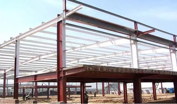
The disadvantageous arrangement of vertical load of steel structure
- 20 Jun 2020
- steel structure
1.Combined method of span calculation
The live load is applied to the structure layer by layer and span by span, and the internal forces of the whole steel structure are calculated respectively. According to different members, different sections and different types of internal forces, the most unfavorable internal forces are combined. There are different live load arrangements (spans x layers). In order to reduce the calculation work, the most unfavorable distribution of roof live load may not be considered, but full distribution may be considered.

2 Most unfavorable load location method
In order to find the most unfavorable internal force of a given section, the live load layout that produces the most unfavorable internal force can be determined directly according to the influence line method.
In order to find the most unfavorable layout of live load of the maximum positive moment MC of section C in the midspan of a certain span beam AB, the influence line of MC can be made first, that is, to release the corresponding constraint (change point C to hinge), and replace it with the positive constraint, so that the steel structure will generate unit virtual displacement along the positive binding force θ C = 1, thus the virtual displacement diagram of the whole structure can be obtained.
According to the principle of virtual displacement, in order to find the maximum positive bending moment in the AB span of the beam, the active load is arranged for the inter span structure with positive virtual displacement. That is to say, in addition to the live load that must be arranged for the span, the other spans shall be arranged alternately, and at the same time, they shall also be arranged alternately in the vertical direction to form a chessboard shaped spacing arrangement. It can be seen that when the AB span reaches the maximum moment in the middle of the span, the most unfavorable arrangement of the live load will also make the moment in the middle of the other arrangement of the live load span reach the maximum. Therefore, as long as the secondary checkerboard live load is arranged, the maximum positive moment of all beams in the whole frame can be obtained.
The most unfavorable arrangement of the live load for the maximum negative moment at the beam end or the maximum moment at the column end can also be obtained by the above method.
The most unfavorable arrangement of the live load of the maximum axial force of the column is that in each layer above the column, the beam span adjacent to the column is full of live load.
3 Layered combination method
(1)For beams, only the unfavorable arrangement of the live load of this layer is considered, and the influence of the live load of other layers is not considered. Therefore, the layout method is the same as the most unfavorable layout method of the live load of the continuous beam.
(2) For the moment at the end of the column, only the influence of the live load of the adjacent upper and lower layers of the column is considered, and the influence of the live load of other layers is not considered.
(3) For the maximum axial force of the column, the case of full live load on the beam adjacent to the column in all layers above the layer is considered, but for the upper live load not adjacent to the column, only the transmission of the axial force is considered, and the effect of the bending moment is not considered.
4 Full load method
When the internal force generated by the live load is far less than that generated by the dead load and horizontal force, the most unfavorable arrangement of the live load can be ignored, and the live load can be applied to all frame beams at the same time, so that the internal force obtained at the support is very similar to the internal force obtained by the most unfavorable load location method, and the internal force can be combined directly. However, the bending moment in the middle of the beam is smaller than that of the most unfavorable load location method. Therefore, the bending moment in the middle of the beam should be multiplied by a factor of 1.1-1.2 to increase.